Fabricating a Shelter 2.0
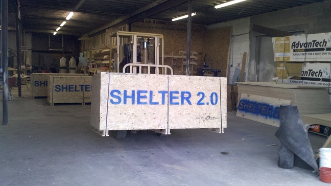
Shelter 2.0 is a digitally fabricated Open Design project created by Robert Bridges and Bill Young. It was originally created as transitional housing after disasters to fill the need for housing between a tent and a permanent home. The design has since been built all over the world, mostly as temporary housing but also as sheds and team building exercises in schools and community groups |

What You’ll need:
1) The project files 2) Either a full version of VCarve or Aspire or the Trial version of VCarve, available at www.vectric.com 3) a 48”x96” ShopBot or other CNC machine. The files were created to be cut on a ShopBot PRSAlpha...if you’ll be cutting on something different you may need to modify speeds and cut depths to suit the machine 3) 3 sheets @ nominal ¾” Advantech or Exterior plywood. We’ve tried really hard to make the Shelter 2.0 design “material agnostic” so that it can be cut from a variety of material thicknesses without having to measure each one. 4) 12 sheets @ nominal ½” exterior plywood. We’ve experimented with OSB and REALLY wanted it to work because it's pretty cheap, but it just doesn't have the strength or stability needed for long-term use. Your mileage may vary. 5) 3 sheets @ nominal 1/8” coroplast or other thin sheet materials for ceiling 6) A 28” x 20” piece of 3/16” Acrylic for each window needed 7) ¼” or 6mm bit |
Files:The files to fabricate the 8’x8’ Shelter 2.0 design have been specially tagged so that they can be opened and toolpathed in the Trial version of VCarve. This allows them to be slightly modified and toolpathed by fabricators without the full version of VCarve or Aspire, increasing the reach of the Shelter 2.0 design. Many thanks to the Vectric crew for making this possible |
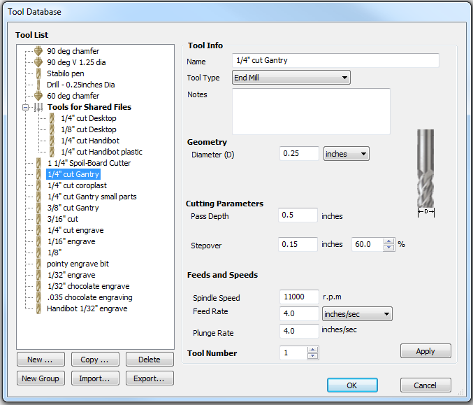
Bits:All the files have been initially toolpathed to cut with a two-flute ¼” bit…that’s what we use to cut them in our shop. We’ve created 2 bits in our toolpath database with the same geometry but different cutting characteristics. One is more aggressive that we use for cutting large parts, and one is for smaller parts that may require a gentler touch! |
Vacuum Holddown and tabbing:We have homebrew vacuum holddown systems so generally don’t use tabs unless the parts are small, like the splice plates for the ribs and the “hatchets” that the screws go into. These small parts get one tab at the start point which seems to hold well. The exception to that are the long thin pieces like the Purlins and door trim. They get tabs along their length to keep them from chattering while cutting.
If you don’t have a vacuum holddown setup you’ll probably want to use screws to fasten the sheets to your table and tabs to keep the cut parts from moving around. Use the .crv files to find safe spots to place holddown screws and create a toolpath to make shallow dimples to mark their location.
We try to cut small parts first when the vacuum holddown is the best. More surface area makes larger parts easier to hold, so do them last |
Cutting without Vacuum Holddown:There are some toolpathing strategies that can help you cut, with or without a vacuum system. On just about every file we create we spend a little extra time picking the order of cut, and the point in each part where it will start cutting. The goal is to have the parts connected to the sheet for as long as possible before finally cutting them free.
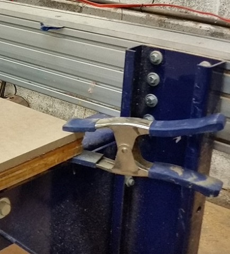
Imagine it as slicing a loaf of bread…you want to hold the loaf firmly while cutting off slices. As you slice, the “slice” is firmly held until the point that it’s cut free. So even with a vacuum holddown we try to put clamps at the far corners of the sheets whenever we can. This also helps keep the waste part of the sheet from “ooching” around as parts are cut out…those clamps are the “hand” that holds the loaf of bread! |
Layers:
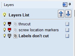
Layers are an easy way to convey details and intent to others, so we try to use descriptive layer names to describe the entities contained in those layers.
Entities in a “screwhole location marker” layer cut shallow dimples that indicate where to eventually drill pilot holes. We cut them with the same ¼” bit that we use to cutout the parts, drilling pilots holes with a drill after the parts are cut, but they could also be cut with a smaller bit or even a V-bit to give a countersink.
Sometimes features like all the holes in all the parts might be on their own layer if they are to be cut using a different strategy than the other parts, such as when using a spiral plunge. It doesn’t hurt to be long-winded in layer names, so we use them to convey useful info about tabbing or ramping.
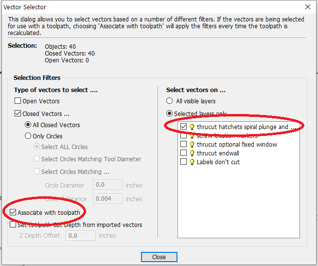
To make toolpathing easier, we have used the “Associate toolpath with layers” option to link each toolpath with the layers that contain those parts. You can read about this in the Vectric help file |
Speeds and Ramping:
We cut these files at 4”/sec and 11,000 rpm spindle speed in the shop, with smaller ½” plywood parts cutting in 2 passes, the larger ½” parts in one pass, and the ¾” plywood in 2 passes. This may be too fast (or slow) for your machine so modify them to do whatever works for you.
We try to ramp into every part that we cut…it makes bits last longer and leaves a better edge. More importantly, since it’s cutting a thinner and thinner bit of material as it gets to the end of the final pass, the cutting force is reduced and the part will stay connected until cutting is finished. For most parts we use a Smooth ramp, varying between 5–8” long depending on how aggressively we’re cutting. With small parts however we almost always use a Spiral ramp, which along with a tab at the start/end point gives better control of the cut and the part. Of course every rule has an exception, and the only exception to our “always ramp” rule is when we’re cutting a shallow feature like a slot or recess for bolt heads…it’s just not needed.
|
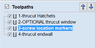
Toolpath naming and organization:The toolpaths are organized based on the way we would cut them. The names are (hopefully) descriptive of the way they are cut and their eventual purpose.
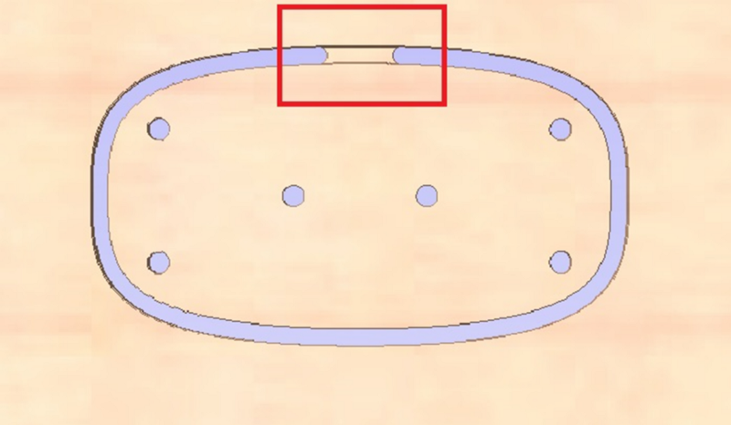
In this example the toolpaths are numbered and meant be cut in that order. Occasionally you’ll find a toolpath with “OPTIONAL” in its name. You may or may not want to run that toolpath depending on the features and endwall options you’ve selected. In this case the thrucut window cutout is optional. |