Arisu Build Guide
Last Updated 3 November 2021
Contents Included
- Acrylic Case
- Hardware
- Bumpons
- PCB
- Hex Socket Driver
Build Steps
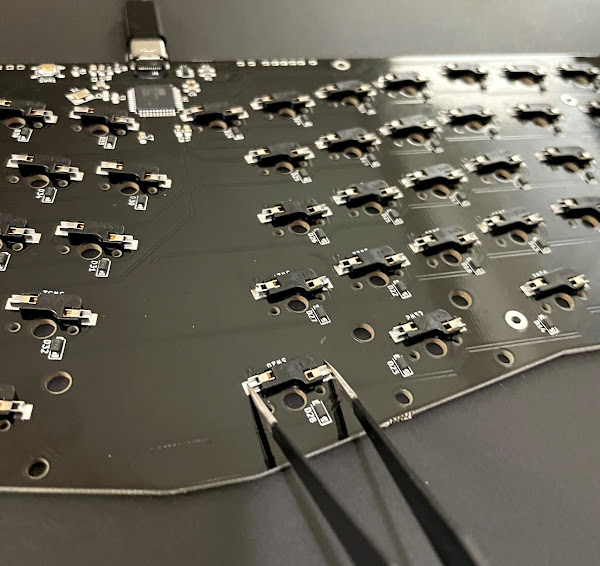
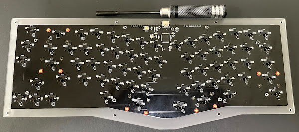
Plug In and Test PCB
- Connect the PCB to your computer with a USB-C cable (not included)
- Short each switch with tweezers to confirm it registers
- More detailed instructions on testing PCBs found here. (Please note that due to a hotswap PCB you will have to use the hotswap pads on the back of the board as shown below)
Install Stabilizers
- Install 5 screw-in or snap-in stabilizers (not included) of your choice to the PCB
- Plate mounted stabilizers are not supported
- Remove the QC sticker from the PCB if present on the top. It will show through the layers of acrylic if your layers are transparent.
Peel Protective Film Off Acrylic
- Peel the protective film off of the acrylic pieces
- Handle the pieces carefully as they can be fragile
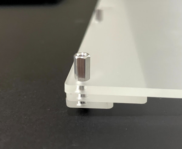
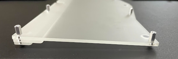
Build the Base of the Case
- Using the included hardware, begin building the case
- Use 4 M2.5x12 screws to go through the two bottom riser pieces and through the back of the base and screw on 4 standoffs
- Very loosely tighten the standoffs! You will need to manipulate them in next steps
- Use 4 M2.5x5 screws to go through the front side of the base plate and install an additional 4 standoffs
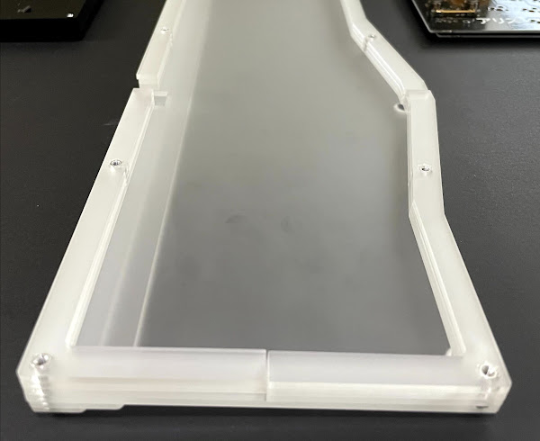
Add 3 Mid Layers
- Add the additional 3 mid layers to the case
- You will have to turn the standoffs in order to orient them properly (which is why we only loosely screwed them on earlier)
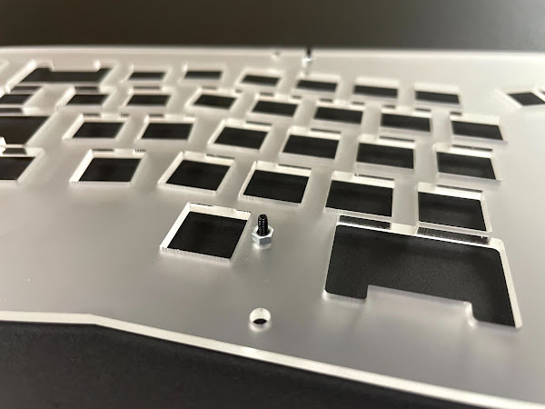
[OPTIONAL] Attach PCB to Plate
- This OPTIONAL step is to attach the PCB to the plate for additional support
- Fasten 8 M2x8 screws and 8 M2x2 hex nuts (the taller of the two hex nuts) to the plate
- The holes located on inside of the plate are for attaching the PCB
- Very loosely screw the hex nuts on! This will help attaching the PCB next
- Flip the plate over and orient the PCB so that the screws go through the mounting holes.
- If you tightened the screws on the plate too tight you may have to loosen them before the PCB will fit.
- Once the PCB is fitted correctly on all 8 mounting holes, use 8 M2x1.6 hex nuts (shorter of the two hex nuts) to fasten the PCB to the plate
- Use the included hex nut driver to make it easier
- Tighten the screws that hold the plate and PCB together so there is not much wobble
- DO NOT OVER TIGHTEN! YOU MAY CRACK THE ACRYLIC OR PCB!
- This OPTIONAL step may cause some switches not to fully seat into the plate. To remedy this if it occurs you can:
- Skip this step (#6) completely by not using the PCB hardware
- Loosen the screws and nuts
- Use something thin and flat such as a flathead screwdriver to help keep the plate propped up
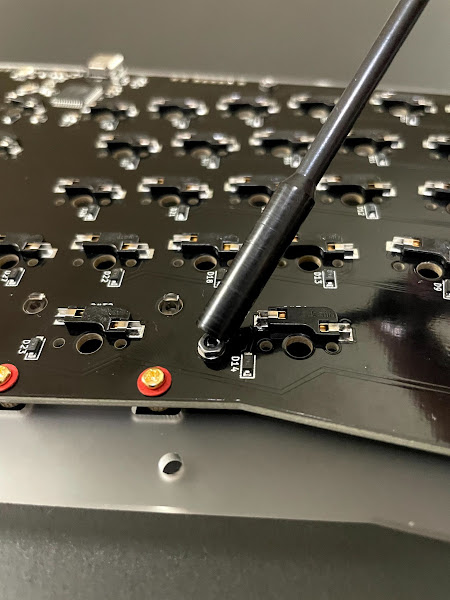
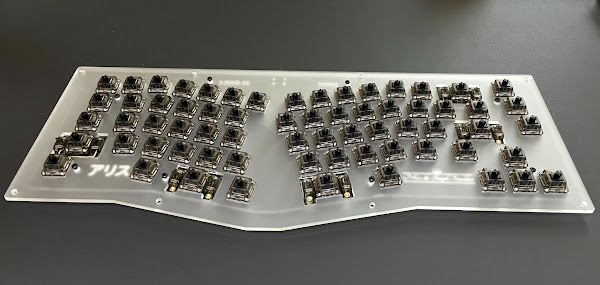
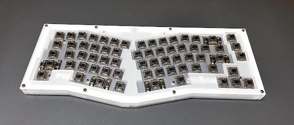
Add Switches
- Install switches (not included) of your choice through the plate into the PCB
- Secure the hotswap pads from the back while inserting switches to ensure the hotswap pads will not come off
- We have successfully used both 3 and 5 pin switches
- We recommend testing your PCB again after installing the switches
- If a key is not registering, take out the switch and confirm there are no bent pins
Install Plate and Remaining Top Layers
- Place the plate and PCB onto the case
- Place the remaining two top layers on the case
- Use 8 M2.5x12 screws to tighten the layers of acrylic
- AGAIN, DO NOT OVER TIGHTEN! YOU MAY CRACK THE ACRYLIC!
Install Keycaps and Bumpons
- Use your preferred keycap set to finish off your build
- Install the bumpons on the bottom of the case as desired
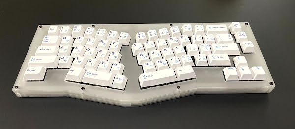
Enjoy
- Plug in your new build with a USB-C cable and enjoy
Keymap Changes
- The PCB should come preflashed with VIA
- Make sure your keyboard is plugged in and open VIA
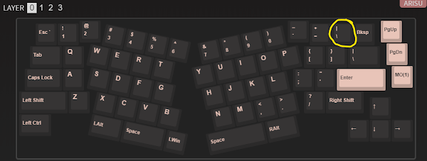
- The current version in the VIA repository is for the original Arisu layout (has split backspace instead of full backspace). Because of this you will see an extra key in VIA as shown below
- You can still make changes to your layout as desired, just know that the extra key is not on your board.
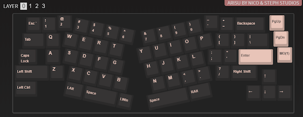
- If you would like to see the “correct” version of your layout, download the JSON from our GitHub and import it into VIA.
- In VIA, once the JSON file is downloaded, click File/Import Keymap and select the JSON file you just downloaded.
- Once loaded you should see the following layout:
- Map your keys as desired
Hardware List
- List of hardware in case you lose screws or standoffs and need to buy extra:
- Case Hardware:
- Plate/PCB Hardware:
- M2x8 Screw
- M2x2 Hex Nut (hex nut between plate and PCB)
- M2x1.6 Hex Nut (hex nut on back of PCB)