MiniDSP C-DSP 8x12 DL: Quick Tuning Guide
- Purpose
- To help fellow hobbyists arrive at a tune that they love
- To provide a consistent process that produces easily replicable results
- To clearly and concisely document the best practice process, as determined by a group of hobbyists/friends on DIYMA, for tuning using a MiniDSP C-DSP 8x12 DL
- Background
- After countless man-hours spent experimenting with different tuning methods, we found better results using a 7-channel tune as compared to the results of the 2-channel method suggested by MiniDSP
- The 7-channel tuning method also requires considerably less effort than the 2-channel method
- The 7-channel method uses Dirac Live (DL) to correct each individual driver, which requires running DL’s sine wave sweeps on each driver, without crossovers
- Once DL has corrected each channel, we set our desired crossovers (XOs); since DL does such a great job at correcting/phase-matching drivers, we expect those XOs to behave in a textbook manner
- System Design & Preparation
- This guide explains how to set up a 4-way active system (3-way active front stage + sub stage)
- 2 tweeters
- 2 midranges
- 2 mid-basses
- Any number of subwoofers running as a single channel; the example in this guide uses a mono amplifier with 2 RCA inputs (i.e. 2 RCA outputs from the C-DSP), powering 2 subs
- Wiring a protective capacitor inline with your tweeters will make this tuning process much easier/safer
- Target curve
- Create your own target curve using Jazzi’s spreadsheet, and click “Export text files”; this will output a file called “REW_Curve_Custom_Overall.txt”
- Open the attached DL target curve heading file; and copy all text
- Paste all text to the top of your “REW_Curve_Custom_Overall.txt” file; save it
- Verify that your “REW_Curve_Custom_Overall.txt” file now looks something like this attached file
- You need an internet connection to use the Dirac Live software
- Plug-in Setup
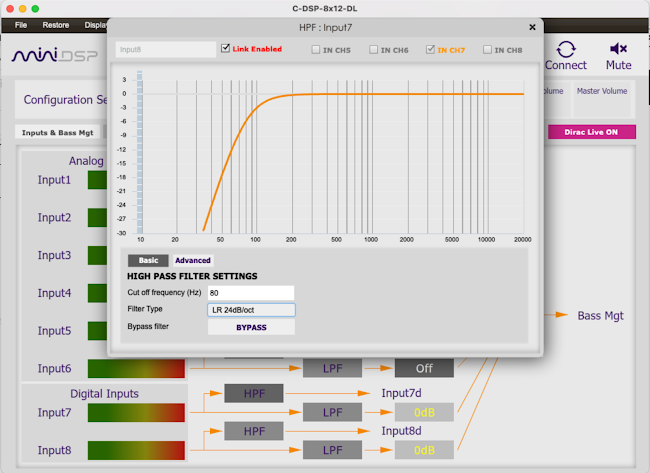
- Inputs & Bass Mgmt Tab
- Determine which inputs you will be using; if using Optical In, Input7 will be your left channel and Input8 will be your right channel
- Click on Input 7’s HPF
- Set “Bypass filter” to BYPASSED
- Link right channel: Click Select Channel → Input 8 → Link
- Click on Input 7’s LPF
- Set “Bypass filter” to BYPASSED
- Link right channel: Click Select Channel → Input 8 → Link
- On the rightmost column, set Input7d/Input8d to 0dB and all unused inputs to Off
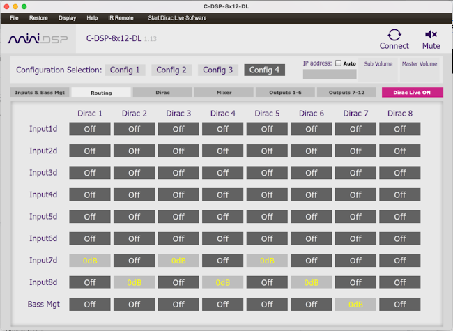
- Routing Tab
- Set Input7 to feed your front stage’s left Dirac channels (i.e. Dirac 1, 3, 5)
- Set Input8 to feed your front stage’s right Dirac channels (i.e. Dirac 2, 4, 6)
- Set Bass Mgt to feed your subwoofer Dirac channel (i.e. Dirac 7)
- Note: The HPF you set on the “Inputs & Bass Mgmt” Tab (4.a.ii) will be cascaded to each of Dirac 1-6, applying the same phase shift to all drivers, helping with phase cohesion
- Note: The LPF you set on the “Inputs & Bass Mgmt” Tab (4.a.iii) will be applied to Dirac 7
- Dirac Tab
- Do nothing at this time
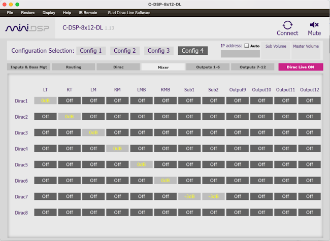
- Mixer Tab
- Set each Dirac channel to feed the corresponding driver/output
- Best practice is to rename the outputs to match the speaker you intend to output to
- Note: In this example, the subwoofer channel (Dirac 7) is outputting to two outputs since the mono amplifier being used has two RCA inputs; as such, the output to each has been reduced to -3dB. Alternatively, you could use one output at 0dB, with a Y-cable if needed. If you have any doubts, simply leave it at 0dB, and Dirac will ultimately level match the drivers (in a later step)
- Outputs 1-6 / Outputs 7-12 Tabs
- Set all outputs to 0dB
- No PEQ
- No Xovers
- Note: if using a ported sub enclosure, consider adding an infrasonic filter:
- On your Sub output (Outputs 7/8), click Xover
- Set a HPF with cut-off frequency = .7*Fb, LR48; do not bypass
- No time delay (0ms)
- Note: the above assumes that you have an inline protective capacitor (or enabled HPF on your amp) for your tweeters. If you do not, you should complete the following steps to set up a protective XO for DL’s sine wave sweeps:
- On your LT output (Output 1), click Xover
- Set a HPF with cut-off frequency = 1.25*Fs, BW12; leave it bypassed
- Click Advanced
- Copy everything after “biquad5,” and before “biquad6,”. Click to see screenshot.
- Click Basic again and ensure the XO is bypassed
- Close the Xover screen, and click on PEQ
- Click on Advanced
- Paste over everything between “biquad1,” and “biquad2,”
- Link right channel: Click on Select Channel → RT → Link
- Note: The above sets the protective XO using PEQ, so you can later apply your main HPF in addition to your protective XO. This approach maintains Dirac’s phase corrections, which will be made with your protective XO in place.
- Mute all unused outputs (e.g. Outputs 9-12)
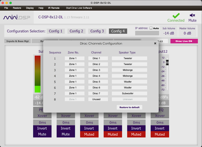
- Dirac Channels Configuration
- In the C-DSP Plugin’s top menu, click Display → Dirac Channels Configuration
- Set the speaker type of each of your Dirac channels (Dirac 1 through 7)
- Set all other channels to Unused
- Dirac Live
- Click Start Dirac Live Software
- Select Device screen: select the C-DSP 8x12 DL as your DL device
- Select Recording Device screen: select your mic; upload appropriate 90 degree calibration file
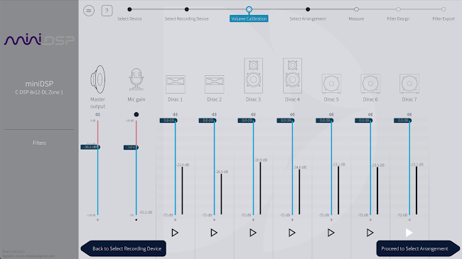
- Volume Calibration screen
- Set Mic gain to 100%
- Put the mic near your nose tip and click play under each channel to test its volume level
- Increase the Master Output to a level that gets your quieter midrange in the -10dB to -15dB range
- When comparing volume levels, look at the quieter speaker in any given pair (i.e. Right tweeter instead of Left tweeter)
- If the quieter driver in any pair is significantly quieter than the quieter driver in another pair, you might consider increasing the amp gain on the quieter pair
- For the subwoofer channel, even if you want the subwoofer to be significantly louder than other drivers, we recommend leaving its volume comparable to other drivers at this step; you can lower the gains for your subwoofer in the C-DSP Plugin accordingly (in the given example, Outputs 7 and 8 were set to -20dB prior to Volume Calibration)
- If you make any adjustments to amp or C-DSP Plugin gains, rerun the Volume Calibration steps
- Select Arrangement screen: Choose “Tightly focused imaging”
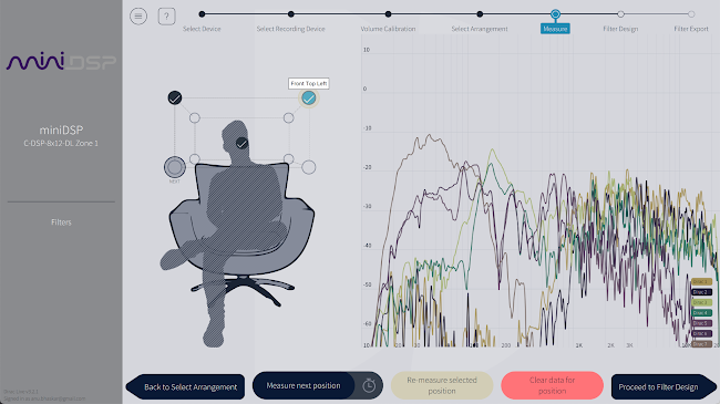
- Measure screen
- Measuring tips
- All measurements should be taken with the mic pointed towards the ceiling
- Lean your seat back such that your body is out of the way, so your mic will have a direct line of sight to each driver
- Silence is golden; if any outside sounds interrupt your measurement (e.g. a plane flying over you, dogs barking, etc.), consider aborting that measurement and re-measuring
- First measurement should be taken at the tip of your nose (in your listening position)
- Measurements 2 through 9 should be taken by creating a rectangular box around the first measurement; ~6” to 12” from the 1st measurement, with the 1st being the center of the box
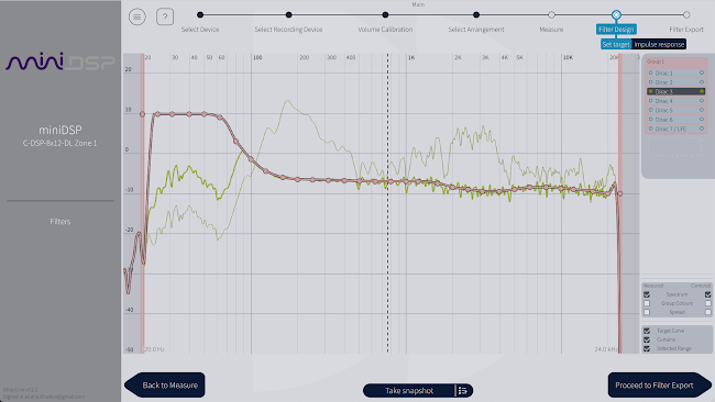
- Filter Design screen
- Click the menu in the top left → Load Target Curve → All Groups -> select target from step 3.c.iv
- In the bottom right, click “Spectrum - Corrected”
- Pull back your curtains
- Click Dirac 2 (Right tweeter, which is usually the “weaker” of the two tweeters)
- Click the curtain (vertical bar in the middle of the screen) and drag it as far right as possible until the corrected line cannot be matched
- Click Dirac 7 (Subwoofer)
- Drag the left curtain as far left as possible such that the target can be met
- Note: if you are using a ported sub, be wary pulling the curtain below the tuning freq
- Review each driver
- Click Dirac 1
- Take a look at the corrected output, and note down the ideal XO point
- Click Dirac 2
- Take a look at the corrected output, and note down the ideal XO point
- Decide on the best trade-off between your XOs from step 2 and 4; note this down
- Repeat for each pair of drivers (and your sub)
- Click Take Snapshot, and name your snapshot something useful to you; copy the name
- Note: it may feel funny to seemingly over-correct a tweeter to hit a curve below its passband. However, these filters are being applied prior to your XOs; once you apply XOs as described in Section 6, then any boost outside of the passband will become negligible.
- Filter Export screen
- Select the DSP Preset that you’d like to output to; paste the name (from 5.g.v) of your snapshot
- After exporting, save your DL project, then quit out of the DL software
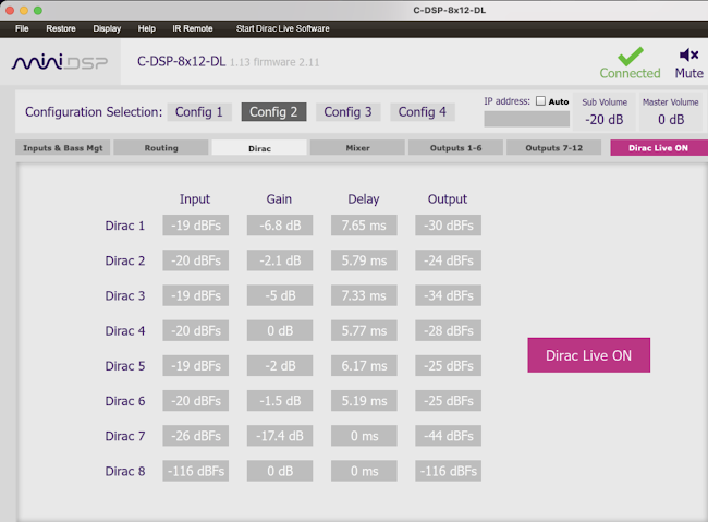
- Now, you can go back to the C-DSP Plugin, click Connect, and take a look at the Dirac tab:
- Delays have been set by Dirac
- Gains have been set, based on Dirac’s own curve
- As a best practice, we recommend taking a screenshot, as you can’t view this tab offline
- Crossovers
- Note the XOs that you intend to use, based on the corrected results from step 5.g.iv.5 (example below):
- Sub-to-midbass: 70Hz LR24 ___________
- Midbass-to-mid: 300Hz LR24 ___________
- Mid-to-tweeter: 4KHz LR24 ___________
- In the C-DSP Plugin, you can now set your XOs
- Inputs & Bass Mgt Tab
- Update Input7/8’s HPF (from 4.a.ii) to the value in 6.a.i; do not bypass
- Update Input7/8’s LPF (from 4.a.iii) to the value in 6.a.i; do not bypass
- Outputs 1-6 / Outputs 7-12 Tabs
- Output 1 (LT)
- Click Xover → apply tweeter’s HPF from 6.a.iii; do not apply a LPF
- Link right channel: Click on Select Channel → RT → Link
- Output 3 (LM)
- Click Xover → apply mid’s HPF from 6.a.ii→ apply mid’s LPF from 6.a.iii
- Link right channel: Click on Select Channel → RM → Link
- Output 5 (LMB)
- Click Xover → apply mid-bass’s LPF from 6.a.ii; do not apply a HPF (due to 6.b.i.1)
- Link right channel: Click on Select Channel → RMB → Link
- Output 7 (Sub1)
- Click Xover → apply mid-bass’s LPF from 6.a.ii (for cascading); if you have a ported enclosure, leave your HPF from 4.e.iii.1.b in place, otherwise do not apply a HPF
- Link right channel: Click on Select Channel → Sub2 → Link
- Note: the C-DSP Plugin’s Master Volume (top right of screen) may need to be adjusted, as the DL software lowers that for its measurement process
- Click File -> Save -> Save current configuration to computer
- Listen
- At this point, you’ve completed your initial tune! Spend some time listening/enjoying!
- Center image verification
- Mute all outputs except the tweeters and verify you have a centered image
- Mute all outputs except the mids and verify you have a centered image
- Mute all outputs except the mid-basses and verify you have a centered image
- If the center image is off-center, you can go through the DL measurement process again, but shift your box in the direction that your box is off-center (e.g. if center is too far left, shift box to the left)
- Volume (if your max volume is too low)
- Take a look at the relative gains that DL set, using the screenshot from step 5.i.iii, and increase the amp gain on whichever channel is at 0dB, by approximately the difference in dB to the next quietest speaker, and then repeat the DL measurement steps (section 5)
- If your max volume is still not loud enough, you can also consider adding up to 6dB of boost to each output in the C-DSP Plugin; be sure to apply to same amount to every output
- Future Iterations (for tinkerers)
- Different measurement locations
- We’ve noticed the DL measurement positions can have immense impact on imaging; after completing this guide, you might consider experimenting with different measurement positions
- Different crossovers
- In 5.g, you can review each driver’s measured/corrected response, by clicking on the specific Dirac channel on the right pane
- For each driver, the range of frequencies that the driver is able to match your target curve (i.e. the corrected response matches the target curve) is your possible “pass-band”
- You can experiment with different crossover values in the Plugin within the pass-band of each driver
- Once you determine what crossovers sound best, be sure to note them down in 6.a
- 4 Dirac groups instead of 1
- Some hobbyists prefer creating four groups during the Filter Design step of the DL process
- You can create additional groups by dragging Dirac channels out of Group 1 on the right pane
- The four groups would be designed as follows:
- Group 1 - Left tweeter + Right tweeter
- Set lower curtain such that no boost is being applied below your protective cap/XO
- Set upper curtain such that no boost is being applied above the worser performing tweeter’s natural top end roll-off
- Group 2 - Left mid + Right mid
- Set lower curtain such that no boost is being applied below the worser performing mid’s natural bottom end roll-off
- Set upper curtain such that no boost is being applied above the worser performing mid’s natural top end roll-off or ~1-2 octaves above the XO from 6.a.iii
- Group 3 - Left mid-bass + Right mid-bass
- Set lower curtain as low as possible such that no boost is being applied below the natural bottom end roll-off or ~1-2 octaves below the XO from 6.a.i
- Set upper curtain such that no boost is being applied above the worser performing mid-bass’s natural top end roll-off or ~1-2 octaves above the XO from 6.a.ii
- Note: it might seem dangerous to boost a mid-bass in the sub-bass frequency range, however this boosting is occurring prior to your XOs. Properly set XOs will protect your drivers, since they are being applied after any boost.
- Group 4 - Subwoofer
- Set lower curtain as low as possible, unless you are using a ported sub, in which case set it such that no boost is being applied below the natural bottom end roll-off
- Set upper curtain as high as possible such that no boost is being applied above the natural top end roll-off or ~1-2 octaves above the XO from 6.a.i
- All Pass Filters (APFs) for improved phase shift in XO band
- TBD[b]
- Measuring in REW
- Some hobbyists have experienced improved results by measuring their final post-Dirac output (all outputs playing together) using mono/correlated pink noise in REW and adjusting accordingly
- Adjust your target curve in DL’s Filter Design step to compensate for any nulls or peaks
- Or, add up to 10 bands of PEQ in the C-DSP Plugin. If you go this route, be sure to apply the same PEQ on every single output so phase shifts are applied on each driver uniformly.
- Footnotes
- Although this guide was written by Anu2g, it is primarily composed of ideas developed by DIYMA members Truthunter and oabeieo, with revision assistance from bertholomey, naiku, and squiers007.
March 15th, 2022
[a]need to update screenshot to show "BYPASSED"
[b]Finalize language for:
1) Once you've finalized your XO points, save the config, then load to the next plugin preset
2) bypass all XOs and add the following APFs:
-Sub @ Sub-to-MB XO
-Midbass @ Sub-to-MB XO and MB-to-Mid XO
-Mid @ Sub-to-MB XO, MB-to-Mid XO, and Mid to Tweet XO
-Tweet @ Sub-to-MB XO and Mid to Tweet XO
3) Run Dirac measurements
4) Bypass APFs and un-bypass XOs
Note: no more cascading the mid-bass LPF to the sub