A
Practical Training Report
On
“Embedded Systems & Robotics”
In the partial fulfillment of the requirement for the award of the degree of
Bachelor of Engineering
(Electronic Instrumentation and Control)
Submitted to: Submitted by:
Mr. A.D.M. Kushwaha Vaibhav Kumar Mishra
Head B.E. V Semester
Dept. of EIC IC0443
Electronic Instrumentation and Control
Global Institute of Technology
Jaipur
Acknowledgement
It was highly educative and interactive to take training at Research and Development Center (Jaipur). A person technically lacks without having practical knowledge, it was a good chance for learning and practicing new things to update our self.
I am highly thankful to the respected R & D In charge Mr. Pankaj Bande, Faculty (E&C) and respected Sir Mr. Puneet Kalia for allowing me to join the Research and Development center and motivating me to do the right things. I also take the opportunity to thanks Mr. Deepak Kashyap for his precious guidance in field of Robotics and interfacing circuits and devices.
Preface
An engineer has to serve the market, for that one must know about the demands and requirements in the market, the way of tackling the hurdles and find a way of working out for their solutions at the right place.
After the completion of four year degree course an engineer must have a thorough knowledge about the theory and practical. For this one must be practically sound with theory aspects.
To make the engineer good at practical the engineering courses provides a 5-6 weeks industrial training where one gets the opportunity to apply the theory in practical processes and production.
We have been lucky to get a chance for undergoing this training at Research and Development center in Jaipur. This report has been prepared on the basis of knowledge acquired by us during training period of 40 days at the center.
Contents
- Acknowledgement ………………….. (i)
- Preface ………………….. (ii)
- Contents ………………….. (iii)
- Introduction to Embedded systems ………………….. 5
- Basic Components …………………… 7
- Parallel Port Basics …………………… 15
- Introduction to Microcontrollers ………………….. 22
- Introduction to Robotics ………………….. 34
- Conclusion …………………… 56
- Bibliography …………………… 57
Embedded Systems
Introduction
An embedded system is a special-purpose system in which the computer is completely encapsulated by the device it controls. Unlike a general-purpose computer, such as a personal computer, an embedded system performs pre-defined tasks, usually with very specific requirements. Since the system is dedicated to a specific task, design engineers can optimize it, reducing the size and cost of the product. Embedded systems are often mass-produced, so the cost savings may be multiplied by millions of items.
Handheld computers or PDAs are generally considered embedded devices because of the nature of their hardware design, even though they are more expandable in software terms. This line of definition continues to blur as devices expand.
Examples of embedded systems
- automatic teller machines (ATMs)
- avionics, such as inertial guidance systems, flight control hardware/software and other integrated systems in aircraft and missiles
- cellular telephones and telephone switches
- computer equipment such as routers and printers
- engine controllers and antilock brake controllers for automobiles
- home automation products, like thermostats, air conditioners, sprinklers, and security monitoring systems
- handheld calculators
- household appliances, including microwave ovens, washing machines, television sets, DVD players/recorders
- medical equipment
- handheld computers
- videogame consoles
The first recognizably modern embedded system was the Apollo Guidance Computer, developed by Charles Stark Draper at the MIT Instrumentation Laboratory. Each flight to the moon had two. They ran the inertial guidance systems of both the command module and LEM.
At the project's inception, the Apollo guidance computer was considered the riskiest item in the Apollo project. The use of the then new monolithic integrated circuits, to reduce the size and weight, increased this risk.
The first mass-produced embedded system was the Autonetics D-17 guidance computer for the Minuteman missile, released in 1961. It was built from discrete transistor logic and had a hard disk for main memory. When the Minuteman II went into production in 1966, the D-17 was replaced with a new computer that was the first high-volume use of integrated circuits. This program alone reduced prices on quad nand gate ICs from
Characteristics
Embedded systems are designed to do some specific task, rather than be a general-purpose computer for multiple tasks. Some also have real-time performance constraints that must be met, for reason such as safety and usability; others may have low or no performance requirements, allowing the system hardware to be simplified to reduce costs.
For high volume systems such as portable music players or mobile phones, minimizing cost is usually the primary design consideration. Engineers typically select hardware that is just “good enough” to implement the necessary functions. For example, a digital set-top box for satellite television has to process large amounts of data every second, but most of the processing is done by custom integrated circuits. The embedded CPU "sets up" this process, and displays menu graphics, etc. for the set-top's look and feel.
The software written for embedded systems is often called firmware, and is stored in ROM or Flash memory chips rather than a disk drive. It often runs with limited hardware resources: small or no keyboard, screen, and little RAM memory.
Embedded systems reside in machines that are expected to run continuously for years without errors and in some cases recover by them if an error occurs. Therefore the Software is usually developed and tested more carefully than that for Personal computers, and unreliable mechanical moving parts such as Disk drives, switches or buttons are avoided. Recovery from errors may be achieved with techniques such as a watchdog timer that resets the computer unless the software periodically notifies the watchdog.
User interfaces
Embedded systems range from no user interface at all - dedicated only to one task - to full user Interfaces similar to desktop operating systems in devices such as PDAs. In between are devices with small character- or digit-only displays and a few buttons. Therefore usability considerations vary widely.
On larger screens, a touch-screen or screen-edge soft buttons also provides good flexibility while minimizing space used. The advantage of this system is that the meaning of the buttons can change with the screen, and selection can be very close to the natural behavior of pointing at what's desired.
Basic Electronic Components
Resistors
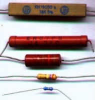
Resistors are components that have a predetermined resistance. Resistance determines how much current will flow through a component. Resistors are used to control voltages and currents. A very high resistance allows very little current to flow. Air has very high resistance. Current almost never flows through air. (Sparks and lightning are brief displays of current flow through air. The light is created as the current burns parts of the air.) A low resistance allows a large amount of current to flow. Metals have very low resistance. That is why wires are made of metal. They allow current to flow from one point to another point without any resistance. Wires are usually covered with rubber or plastic. This keeps the wires from coming in contact with other wires and creating short circuits. High voltage power lines are covered with thick layers of plastic to make them safe, but they become very dangerous when the line breaks and the wire is exposed and is no longer separated from other things by insulation.
Resistance is given in units of ohms. (Ohms are named after Mho Ohms who played with electricity as a young boy in Germany.) Common resistor values are from 100 ohms to 100,000 ohms. Each resistor is marked with colored stripes to indicate its resistance.
Variable Resistors
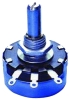
Variable resistors are also common components. They have a dial or a knob that allows you to change the resistance. This is very useful for many situations. Volume controls are variable resistors. When you change the volume you are changing the resistance which changes the current. Making the resistance higher will let less current flow so the volume goes down. Making the resistance lower will let more current flow so the volume goes up. The value of a variable resistor is given as its highest resistance value. For example, a 500 ohm variable resistor can have a resistance of anywhere between 0 ohms and 500 ohms. A variable resistor may also be called a potentiometer (pot for short).
Capacitors
Now suppose you want to control how the current in your circuit changes (or not changes) over time. Now why would you? Well radio signals require very fast current changes. Robot motors cause current fluctuations in your circuit which you need to control. What do you do when batteries cannot supply current as fast as you circuit drains them? How do you prevent sudden current spikes that could fry your robot circuitry? The solution to this is capacitors.


Capacitors are like electron storage banks. If your circuit is running low, it will deliver electrons to your circuit.
In our water analogy, think of this as a water tank with water always flowing in, but with drainage valves opening and closing. Since capacitors take time to charge, and time to discharge, they can also be used for timing circuits. Timing circuits can be used to generate signals such as PWM or be used to turn on/off motors in solar powered BEAM robots.
Quick note, some capacitors are polarized, meaning current can only flow one direction through them. If a capacitor has a lead that is longer than the other, assume the longer lead must always connect to positive.
Power surge /drainage management
The problem with using robot components that drain a large amount of power is sometimes your battery cannot handle the high drain rate, Motors and servos being perfect examples. This would cause a system wide voltage drop, often resetting your microcontroller, or at least causing it to not work properly. Just a side note, it is bad to use the same power source for both your circuit and your motors. So don't do it.
Or suppose your robot motors are not operating at its full potential because the battery cannot supply enough current, the capacitor will make up for it. The solution is to place a large electrolytic capacitor between the source and ground of your power source. Get a capacitor that is rated at least twice the voltage you expect to go through it. Have it rated at 1mF-10mF for every amp required. For example, if your 20V motors will use 3 amps, use a 3mF-30mF 50V rated capacitor. Exactly how much will depend on how often you expect your motor to change speed and direction, as well as momentum of what you are actuating. Just note that if your capacitor is too large, it may take a long time to charge up when you first turn your robot on. If it is too small, it will drain of electrons and your circuit will be left with a deficit. It is also bad to allow a large capacitor to remain fully charged when you turn off your robot. Some things could accidentally short and fry. So use a simple power on LED in your motor circuit to drain the capacitor after your robot is turned off. If your capacitor is not rated properly for voltage, then can explode with smoke. Fortunately they do not overheat if given excessive amounts of current. So just make sure your capacitor is rated higher than your highest expected.
Capacitors can also be used to prevent power spikes that could potentially fry circuitry. Next to any on/off switch or anything that that could affect power suddenly should have a capacitor across it?
Capacitors can eliminate switch bouncing. When you flip a mechanical switch, the switch actually bounces several times within a microsecond range. Normally this is too small of a time for anyone to care (or even notice), but note that a microcontroller can take hundreds of readings in a single microsecond. So if your robot was counting the number of times a switch is flipped, a single flip can count as dozens. So how do you stop this? Use a small ceramic capacitor! Just experiment until you find the power capacitance value.
Diodes
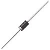
Diodes are components that allow current to flow in only one direction. They have a positive side (leg) and a negative side. When the voltage on the positive leg is higher than on the negative leg then current flows through the diode (the resistance is very low). When the voltage is lower on the positive leg than on the negative leg then the current does not flow (the resistance is very high). The negative leg of a diode is the one with the line closest to it. It is called the cathode. The positive end is called the anode.
Usually when current is flowing through a diode, the voltage on the positive leg is 0.65 volts higher than on the negative leg.
Switches
Switches are devices that create a short circuit or an open circuit depending on the position of the switch. For a light switch, ON means short circuit (current flows through the switch, and lights light up.) When the switch is OFF, that means there is an open circuit (no current flows, lights go out.
When the switch is ON it looks and acts like a wire. When the switch is OFF there is no connection.
The LED

An LED is the device shown above. Besides red, they can also be yellow, green and blue. The letters LED stand for Light Emitting Diode. The important thing to remember about diodes (including LEDs) is that current can only flow in one direction.
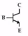
The Transistor
Transistors are basic components in all of today's electronics. They are just simple switches that we can use to turn things on and off. Even though they are simple, they are the most important electrical component. For example, transistors are almost the only components used to build a Pentium processor. A single Pentium chip has about 3.5 million transistors. The ones in the Pentium are smaller than the ones we will use but they work the same way.
Transistors that we will use in projects look like this:
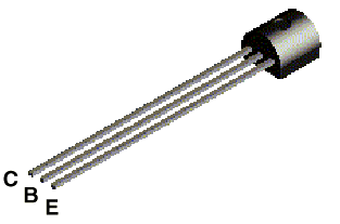
The transistor has three legs, the Collector (C), Base (B), and Emitter (E). Sometimes they are labeled on the flat side of the transistor. Transistors always have one round side and one flat side. If the round side is facing you, the Collector leg is on the left, the Base leg is in the middle, and the Emitter leg is on the right.
Transistor Symbol
The following symbol is used in circuit drawings (schematics) to represent a transistor.
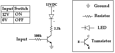
Basic Circuit
The Base (B) is the On/Off switch for the transistor. If a current is flowing to the Base, there will be a path from the Collector (C) to the Emitter (E) where current can flow (The Switch is On.) If there is no current flowing to the Base, then no current can flow from the Collector to the Emitter. (The Switch is off.)
Below is the basic circuit we will use for all of our transistors.
Relays
A relay is usually an electromechanical device that is actuated by an electrical current. The current flowing in one circuit causes the opening or closing of another circuit. Relays are like remote control switches and are used in many applications because of their relative simplicity, long life, and proven high reliability. They are used in a wide variety of applications throughout industry, such as in telephone exchanges, digital computers and automation systems.
How do relays work?
All relays contain a sensing unit, the electric coil, which is powered by AC or DC current. When the applied current or voltage exceeds a threshold value, the coil activates the armature, which operates either to close the open contacts or to open the closed contacts. When a power is supplied to the coil, it generates a magnetic force that actuates the switch mechanism. The magnetic force is, in effect, relaying the action from one circuit to another. The first circuit is called the control circuit; the second is called the load circuit. A relay is usually an electromechanical device that is actuated by an electrical current.
The current flowing in one circuit causes the opening or closing of another circuit.
Types of Relays
There are two basic classifications of relays:
- Electromechanical Relay
- Solid State Relay.
Electromechanical relays have moving parts, whereas solid state relays have no moving parts. Advantages of Electromechanical relays include lower cost, no heat sink is required, multiple poles are available, and they can switch AC or DC with equal ease.
- Electromechanical Relays
General Purpose Relay: The general-purpose relay is rated by the amount of current its switch contacts can handle. Most versions of the general-purpose relay have one to eight poles and can be single or double throw. These are found in computers, copy machines, and other consumer electronic equipment and appliances.
Power Relay: The power relay is capable of handling larger power loads – 10-50 amperes or more.
They are usually single-pole or double-pole units.
Contactor: A special type of high power relay, it’s used mainly to control high voltages and currents in industrial electrical applications. Because of these high power requirements, contactors always have double-make contacts.
Time-Delay Relay: The contacts might not open or close until some time interval after the coil has been energized. This is called delay-on-operate. Delay-on-release means that the contacts will remain in their actuated position until some interval after the power has been removed from the coil.
A third delay is called interval timing. Contacts revert to their alternate position at a specific interval of time after the coil has been energized.
The timing of these actions may be a fixed parameter of the relay, or adjusted by a knob on the relay itself, or remotely adjusted through an external circuit.
- Solid State Relays
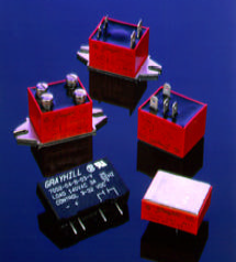
These active semiconductor devices use light instead of magnetism to actuate a switch. The light comes from an LED, or light emitting diode. When control power is applied to the device’s output, the light is turned on and shines across an open space.
On the load side of this space, a part of the device senses the presence of the light, and triggers a solid state switch that either opens or closes the circuit under control.
Often, solid state relays are used where the circuit under control must be protected from the introduction of electrical noises.
Advantages of Solid State Relays include low EMI/RFI, long life, no moving parts, no contact bounce, and fast response.
The drawback to using a solid state relay is that it can only accomplish single pole switching.
Parallel port basics:
In computers, ports are used mainly for two reasons: Device control and communication. We can program PC's Parallel ports for both. Parallel ports are mainly meant for connecting the printer to the PC. But we can program this port for many more applications beyond that.
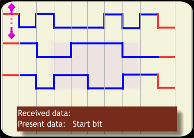
Parallel ports are easy to program and faster compared to the serial ports. But main disadvantage is it needs more number of transmission lines. Because of this reason parallel ports are not used in long distance communications. Let us know the basic difference between working of parallel port and serial port. In serial ports, there will be two data lines: One transmission and one receive line. To send a data in serial port, it has to be sent one bit after another with some extra bits like start bit, stop bit and parity bit to detect errors. But in parallel port, all the 8 bits of a byte will be sent to the port at a time and a indication will be sent in another line. There will be some data lines, some control and some handshaking lines in parallel port. If three bytes of data 01000101 10011100 10110011 is to be sent to the port, following figures will explain how they are sent to the serial and parallel ports respectively. We can understand why parallel port communication is faster compared to that of serial.
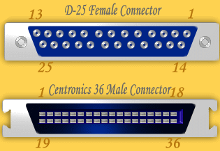
In the PC there will be D-25 type of female connector having 25 pins and in the printer; there will be a 36-pin Centronics connector. Connecting cable will combine these connecters using following convention. Pin structure of D-25 and Centronics connecters are explained bellow.
Normally, data, control and status registers will have following addresses. We need these addresses in programming.
Register | LPT1 | LPT2 |
Data register (Base Address + 0) | 0x378 | 0x278 |
Status register (Base Address + 1) | 0x379 | 0x279 |
Control register (Base Address + 2) | 0x37a | 0x27a |
Note: All the parallel ports do not have bidirectional capability. Earlier parallel ports had only output enabled in data pins since printers only inputs data. But latter, to make parallel port capable of communicating with other devises, bidirectional ports are introduced.
By default, data port is output port. To enable the bidirectional property of the port, we need to set the bit 5 of control register.
To know the details of parallel ports available in your computer, follow this procedure:
- Right click on My Computer, go to "Properties".
- Select the tab Hardware, Click Device manager.
- You will get a tree structure of devices. In that Expand "Ports (Com1 & LPT)".
- Double Click on the ECP Printer Port (LPT1) or any other LPT port if available.
- You will get details of LPT port. Make sure that "Use this Port (enable)" is selected.
- Select tab recourses. In that you will get the address range of port.
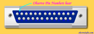
To start programming, you will need a D-25 type Male connector. Its pin structures can be found in the connector as follows:
Programming the Parallel Port in DOS:
To start programming the port, we will use DOS. In DOS we have commands to access the port directly. But, these programs will not work on the systems based on Windows XP, Windows NT or higher versions. For security reasons, higher versions of the windows do not allow accessing the port directly. To program the parallel port in these systems, we need to write kernel mode driver.
When we want to find out whether particular pin of the port is high or low, we need to input the value of corresponding register as a byte. In that, we have to find out whether the corresponding bit is high or low using bitwise operators. We can't access the pins individually. So, you need to know basic bitwise operations.
Main bitwise operators that we need are bitwise AND '&' and bitwise OR '|'. To make a particular bit in a byte high without affecting other bits, write a byte with corresponding bit 1 and all other bits 0; OR it with original byte. Similarly, to make particular bit low, write a byte with corresponding bit 0 and all other bits 1; AND it with original byte.
In Turbo C, there are following functions used for accessing the port:
- outportb( PORTID, data);
- data = inportb( PORTID);
- outport( PORTID, data);
- data = inport( PORTID);
outport() function sends a word to port, inport() reads a word from the port. outportb() sends a byte to port and inportb() reads a byte from the port. If you include DOS.H header, these functions will be considured as macro, otherwise as functions. Function inport() will return a word having lower byte as data at PORTID and higher byte as data at PORTID+2. So, we can use this function to read status and control registers together. inportb() function returns byte at PORTID. outport() writes the lower byte to PORTID and higher byte to PORTID+1. So this can be used to write data and control together. outportb() function write the data to PORTID. outport() and outportb() returns nothing.
Let us start with inputting first. Here is an example program, copy it and run in Turbo C or Borland C without anything connected to parallel port. Then you should see data available in status register and pin numbers 10, 11, 12, 13 and 15 of the parallel port. Pin 11 (active low) is 0 and all other pins are 1 means it is OK.
To understand bitwise operations: you want to find data in pin 15, value of (data & 0x08) will be 0x08 if bit 3 of register is high, 0therwise.
bit no. 7654 3210 | bit no. 7654 3210 |
Interfacing of Seven Segment with Parallel port:-
Apparatus:
Seven segment C-5611, Parallel Port Connector cord, Jumper Wires Bread Board.
Procedure:
1. Open windows 98 as OS
2. Connect the male connector of the parallel port cord to the PC
3. Now connect the Female Connector of cord with seven segment C-5611 as shown in table.
Table: Connection between Seven Segment and Female Connector
Seven Segment Pin No. | Female Connector Pin No. |
1 | 6 |
2 | 5 |
3 | 19 |
4 | 4 |
5 | 9 |
6 | 3 |
7 | 2 |
8 | 20 |
9 | 7 |
10 | 8 |
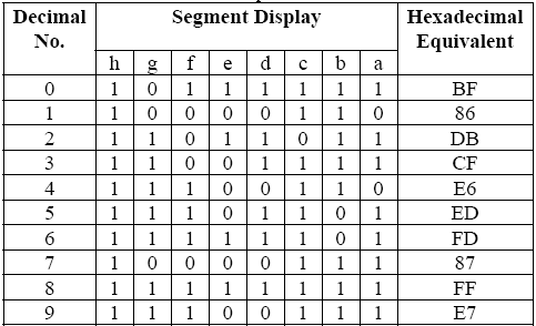
Table: Relationship of decimal No. , Segment Display
and Hexadecimal Equivalent
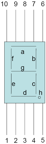
Pin Out of seven segment
Microcontrollers
The 8051 Microcontroller
Overview
The 8051 family of micro controllers is based on an architecture which is highly optimized for embedded control systems. It is used in a wide variety of applications from military equipment to automobiles to the keyboard on your PC. Second only to the Motorola 68HC11 in eight bit processors sales, the 8051 family of microcontrollers is available in a wide array of variations from manufacturers such as Intel, Philips, and Siemens. These manufacturers have added numerous features and peripherals to the 8051 such as I2C interfaces, analog to digital converters, watchdog timers, and pulse width modulated outputs. Variations of the 8051 with clock speeds up to 40MHz and voltage requirements down to 1.5 volts are available. This wide range of parts based on one core makes the 8051 family an excellent choice as the base architecture for a company's entire line of products since it can perform many functions and developers will only have to learn this one platform.
The basic architecture consists of the following features:
One 8051 processor cycle consists of twelve oscillator periods. Each of the twelve oscillator periods is used for a special function by the 8051 core such as op code fetches and samples of the interrupt daisy chain for pending interrupts. The time required for any 8051 instruction can be computed by dividing the clock frequency by 12, inverting that result and multiplying it by the number of processor cycles required by the instruction in question. Therefore, if you have a system which is using an 11.059MHz clock, you can compute the number of instructions per second by dividing this value by 12. This gives an instruction frequency of 921583 instructions per second. Inverting this will provide the amount of time taken by each instruction cycle (1.085 microseconds).
- an eight bit ALU
- 32 discrete I/O pins (4 groups of 8) which can be individually accessed
- two 16 bit timer/counters
- full duplex UART
- 6 interrupt sources with 2 priority levels
- 128 bytes of on board RAM
- separate 64K byte address spaces for DATA and CODE memory
Memory Organization
The 8051 architecture provides the user with three physically distinct memory spaces which can be seen in Figure A - 1. Each memory space consists of contiguous addresses from 0 to the maximum size, in bytes, of the memory space. Address overlaps are resolved by utilizing instructions which refer specifically to a given address space. The three memory spaces function as described below.
Figure A - 1 - 8051 Memory Architecture
The CODE Space
The first memory space is the CODE segment in which the executable program resides. This segment can be up to 64K (since it is addressed by 16 address lines). The processor treats this segment as read only and will generate signals appropriate to access a memory device such as an EPROM. However, this does not mean that the CODE segment must be implemented using an EPROM. Many embedded systems these days are using EEPROM which allows the memory to be overwritten either by the 8051 itself or by an external device. This makes upgrades to the product easy to do since new software can be downloaded into the EEPROM rather than having to disassemble it and install a new EPROM.
Additionally, battery backed SRAMs can be used in place of an EPROM. This method offers the same capability to upload new software to the unit as does an EEPROM, and does not have any sort of read/write cycle limitations such as an EEPROM has. However, when the battery supplying the RAM eventually dies, so does the software in it. Using an SRAM in place of an EPROM in development systems allows for rapid downloading of new code into the target system. When this can be done, it helps avoid the cycle of programming/testing/erasing with EPROM’s, and can also help avoid hassles over an in circuit emulator which is usually a rare commodity. In addition to executable code, it is common practice with the 8051 to store fixed lookup tables in the CODE segment. To facilitate this, the 8051 provides instructions which allow rapid access to tables via the data pointer (DPTR) or the program counter with an offset into the table optionally provided by the accumulator. This means that oftentimes, a table's base address can be loaded in DPTR and the element of the table to access can be held in the accumulator. The addition is performed by the 8051 during the execution of the instruction which can save many cycles depending on the situation.
The DATA Space
The second memory space is the 128 bytes of internal RAM on the 8051, or the first 128 bytes of internal RAM on the 8052. This segment is typically referred to as the DATA segment. The RAM locations in this segment are accessed in one or two cycles depending on the instruction. This access time is much quicker than access to the XDATA segment because memory is addressed directly rather than via a memory pointer such as DPTR which must first be initialized. Therefore, frequently used variables and temporary scratch variables are usually assigned to the DATA segment. Such allocation must be done with care, however, due to the limited amount of memory in this segment.
Variables stored in the DATA segment can also be accessed indirectly via R0 or R1. The register being used as the memory pointer must contain the address of the byte to be retrieved or altered. These instructions can take one or two processor cycles depending on the source/destination data byte.
The DATA segment contains two smaller segments of interest. The first sub segment consists of the four sets of register banks which compose the first 32 bytes of RAM. The 8051 can use any of these four groups of eight bytes as its default register bank. The selection of register banks is changeable at any time via the RS1 and the RS0 bits in the Processor Status Word (PSW). These two bits combine into a number from 0 to 3 (with RS1 being the most significant bit) which indicates the register bank to be used.
Register bank switching allows not only for quick parameter passing, but also opens the door for simplifying task switching on the 8051.
The second sub-segment in the DATA space is a bit addressable segment in which each bit can be individually accessed. This segment is referred to as the BDATA segment. The bit addressable segment consists of 16 bytes (128 bits) above the four register banks in memory. The 8051 contains several single bit instructions which are often very useful in control applications and aid in replacing external combinatorial logic with software in the 8051 thus reducing parts count on the target system. It should be noted that these 16 bytes can also be accessed on a "byte-wide" basis just like any other byte
in the DATA space.
Special Function Registers
Control registers for the interrupt system and the peripherals on the 8051 are contained in internal RAM at locations 80 hex and above. These registers are referred to as special function registers (or SFRs for short). Many of them are bit addressable. The bits in the bit addressable SFRs can either be accessed by name, index or bit address. Thus, you can refer to the EA bit of the Interrupt Enable SFR as EA, IE.7, or 0AFH. The SFRs control things such as the function of the timer/counters, the UART, and the interrupt sources as well as their priorities. These registers are accessed by the same set of instructions as the bytes and bits in the DATA segment. A memory map of the SFRs indicating the registers which are bit addressable is shown in Table A - 1.
The IDATA Space
Certain 8051 family members such as the 8052 contain an additional 128 bytes of internal RAM which reside at RAM locations 80 hex and above. This segment of RAM is typically referred to as the IDATA segment. Because the IDATA addresses and the SFR addresses overlap, address conflicts between IDATA RAM and the SFRs are resolved by the type of memory access being performed, since the IDATA segment can only be accessed via indirect addressing modes.
The XDATA Space
The final 8051 memory space is 64K in length and is addressed by the same 16 address lines as the CODE segment. This space is typically referred to as the external data memory space (or the XDATA segment for short). This segment usually consists of some sort of RAM (usually an SRAM) and the I/O devices or external peripherals to which the 8051 must interface via its bus. Read or write operations to this segment take a minimum of two processor cycles and are performed using either DPTR, R0, or R1. In the case of DPTR, it usually takes two processor cycles or more to load the desired address in addition to the two cycles required to perform the read or write operation. Similarly, loading R0 or R1 will take minimum of one cycle in addition to the two cycles imposed by the memory access itself. Therefore, it is easy to see that a typical operation with the XDATA segment will, in general, take a minimum of three processor cycles. Because of this, the DATA segment is a very attractive place to store any frequently used variables.
It is possible to fill this segment entirely with 64K of RAM if the 8051 does not need to perform any I/O with devices in its bus or if the designer wishes to cycle the RAM on and off when I/O devices are being accessed via the bus. Methods for performing this technique will be discussed in chapters later in this book.
Bit processing and Boolean logic
The 8051 contains a single bit Boolean processor which can be used to perform logical operations on any of the 128 addressable bits in the BIT segment, the 128 addressable bits in the SFRs, and any of the 32 I/O lines (port 0 through port 3). The 8051 can perform OR, AND, XOR, complement, set, and clear operations on bits as well as moving bit values as one would normally move byte values.
MOV C, 22H ; move the bit value at address
; 22H to the carry bit
ORL C, 23H ; or the bit value at address
; 23H into the carry bit
ANL 24H, C ; and the carry bit into bit
; address 24H
There are also conditional branches which use addressed bits as the condition. One such branch which is especially useful is the “jump if bit is set and clear bit” instruction. This "branch and clear" can be performed in two processor cycles and saves a cycle or two over splitting the jump and the clear into two separate op codes. As an example, suppose that you had to write a routine which waited for pin P0.0 to set, but could not wait indefinitely. This routine would have to decrement a timeout value and exit the polling loop when this timeout is exceeded. When pin P0.0 sets, the processor must force it back to 0 and exit the polling loop. With normal logic flow, the routine would look like the following.
MOV timeout, #TO_VAL ; set the timeout value
L2: JB P0.0, L1 ; check the bit
DJNZ timeout, L2 ; decrement the timeout counter
; and sample again
L1: CLR P0.0 ; force P0.0 to logic level 0
RET ; exit the routine
Using the JBC instruction, the same routine would be coded as follows.
MOV timeout, #TO_VAL ; set the timeout value
L2: JBC P0.0, L1 ; check the bit and force P0.0
; to logic level 0 if set
DJNZ timeout, L2 ; decrement the timeout counter
L1: RET ; exit the routine
While the second routine may not offer a huge amount of savings in the code, it does make the code a little simpler and more elegant. There will be many situations in your use of assembly code on the 8051 controller where this instruction will come in handy.
On-Board Timer/Counters
The standard 8051 has two timer/counters (other 8051 family members have varying amounts), each of which is a full 16 bits. Each timer/counter can be function as a free running timer (in which case they count processor cycles) or can be used to count falling edges on the signal applied to their respective I/O pin (either T0 or T1). When used as a counter, the input signal must have a frequency equal to or lower than the instruction cycle frequency divided by 2 (i.e.: the oscillator frequency /24) since the incoming signal is sampled every instruction cycle, and the counter is incremented only when a 1 to 0 transition is detected (which will require two samples). If desired, the timer/counters can force a software interrupt when they overflow.
The TCON (Timer Control) SFR is used to start or stop the timers as well as hold the overflow flags of the timers. The TCON SFR is detailed below in Table A - 7. The timer/counters are started or stopped by changing the timer run bits (TR0 and TR1) in TCON. The software can freeze the operation of either
timer as well as restart the timers simply by changing the TRx bit in the TCON register. The TCON register also contains the overflow flags for the timers. When the timers overflow, they set their respective flag (TF0 or TF1) in this register. When the processor detects a 0 to 1 transition in the flag, an interrupt occurs if it is enabled. It should be noted that the software can set or clear this flag at any
time. Therefore, an interrupt can be prevented as well as forced by the software.
Timer Control Register (TCON) - Bit Addressable
TF1 Timer 1 overflow flag. Set when timer 1 overflows. Cleared by processor upon vectoring to the interrupt service routine.
TR1 Timer 1 control bit. If TR1=1, timer 1 runs. If TR1=0, timer 1 stops.
TF0 Timer 0 overflow flag. Set when timer 0 overflows. Cleared by processor upon vectoring to the interrupt service routine.
TR0 Timer 0 control bit. If TR0=1, timer 1 runs. If TR0=0, timer 1 stops.
IE1 External interrupt 1 edge flag. Set when a valid falling edge is detected at pin P3.3. Cleared by hardware when the interrupt is serviced.
IT1 Interrupt 1 type control bit. If IT1=1, interrupt 1 is triggered by a falling edge on P3.3. If IT1=0, interrupt 1 is triggered by a low logic level on P3.3
IE0 External interrupts 0 edge flag. Set when a valid falling edge is detected at pin P3.2. Cleared by hardware when the interrupt is serviced.
IT0 Interrupt 0 type control bit. If IT0=1, interrupt 1 is triggered by a falling edge on P3.2. If
IT0=0, interrupt 0 is triggered by a low logic level on P3.2
The timers are configured by altering the value in the TMOD (timer mode) SFR. By changing TMOD, the software can control the mode of both timers as well as the source they use to count (the signal at their I/O pin or the processor cycles). The upper nibble of TMOD controls the operation of timer 1 and the low nibble controls the operation of timer 0. The layout of the TMOD register (which is not bit addressable) is shown below.
The source for the timer can be configured by altering the C/T bit in TMOD. Setting this bit to true will force the timer to count pulses on the I/O pin assigned to it. Setting this bit false will force counting of processor cycles. When a timer is forced to count processor cycles it can do this either under hardware or software control. Software control is commanded by setting the GATE bit of TMOD to 0. In this case, the timer will count any time its TRx bit in the TCON register is high. In the hardware control mode, both the TRx bit and the INTx pin on the chip must be high for the timer to count. When a low is detected at the INTx pin, the timer will stop. This is useful for measuring pulse widths of signals on the INTx pin if one does not mind surrendering an external interrupt source to the incoming signal.
Timer Mode 0 and Mode 1
The timer/counters can be operated in one of four modes, under software control. In mode 0, the timer/counter will behave like a 13 bit counter. When the counter overflows, the TF0 or TF1 (timer flag) bit in the TCON (timer control) SFR is set. This will cause the appropriate timer interrupt (assuming it is enabled). Both timer 0 and timer 1 operate in the same way for mode 0. The operation of the timers in mode 1 is the same as it is for mode 0 with the exception that all sixteen bits of the timer are used instead of only thirteen.
Timer Mode 2
In mode 2, the timer is set up as an eight bit counter which automatically reloads whenever an overflow condition is detected. The low byte of the timer (TL0 or TL1) is used as the counter and the high byte of the timer (TH0 or TH1) holds the reload value for the counter. When the timer/counter overflows, the value in THx is loaded into TLx and the timer continues counting from the reload value. Both timer 0 and timer 1 function identically in mode 2. Timer 1 is often used in this mode to generate baud rates for the UART.
Timer Mode 3
In mode 3, timer 0 becomes two eight bit counters which are implemented in TH0 and TL0. The counter implemented in TL0 maintains control of all the timer 0 flags, but the counter in TH0 takes over the control flags in TCON from timer 1. This implies that timer 1 can no longer force interrupts, however, it can be used for any purpose which will not require the overflow interrupt such as a baud rate generator for the UART, or as a timer/counter which is polled by the software. This is useful when an application must use a UART mode which requires baud rate generation from timer 1 and also requires two timer/counters. When timer 1 is placed in mode 3 it simply freezes.
On-Board UART
The 8051 features an on board, full duplex UART which is under software control. The UART is configured via the SCON (Serial CONtrol) SFR. The SCON register allows the user to select the UART mode, enable reception, and check UART status. SCON is illustrated in Table A - 10.
The UART features a one byte buffer for incoming data so that another byte can be ringing into the UART before the last byte has been read. However, after one byte time, the buffer will be overwritten as the next incoming byte is completed. Therefore, the software must be capable of responding to an incoming byte within one serial byte time. This is also true for outgoing data assuming that it is required to be back to back.
The 8051 supports standard ten bit frames as well as an eleven bit frame designed for inter processor communications and a high speed 8 bit shift register mode. The baud rate is variable for all modes except the eight bit shift mode and one of the inter processor modes.
UART Mode 0
In mode 0 the UART acts as an eight bit shift register clocking data in and out at a baud rate of 1/12th of the oscillator frequency. Data is sent LSB first and enters and exits the UART via the RXD pin. Therefore mode 0 does not support full duplex since the RXD pin is used for all incoming and outgoing data and the TXD pin is used to echo the shift clock. This mode is useful for situations in which the micro controller is used to interface to a serial device such as an EEPROM which has a serial eight bit interface format. Transmission of a byte begins when the SBUF SFR is the destination register of a move instruction. At
this point, the eight bits are clocked out and the TI bit is set when the transmission of the eighth bit is complete. Reception begins when the REN bit of the SCON register is set true. The RI bit is set when the eighth bit is clocked in.
UART Mode 1
In mode 1 of the UART, 8 data bits are transmitted in a ten bit frame: one start bit, eight data bits, and one stop bit. This mode is suitable for communications to most serial devices including personal computers. The baud rate is variable and is controlled by the overflow rate of timer 1 in the auto reload mode or, optionally, by timer 2 in the baud rate generating mode on an 8052. Overflow interrupts should be disabled for the timer being used to generate the baud rate. The SMOD bit in the PCON (power control) SFR can be set high to double the baud rate implemented by the UART. The TI and RI interrupt signals are activated halfway through the transmission or reception of the stop bit. Typically, this will allow the software time to respond to the interrupt and load SBUF with the next byte in back to back during data block transfers. The amount of processing time available depends on the baud rate in use and the oscillator frequency being used to drive the 8051. If timer 1 is going to be used to generate the desired baud rate of the UART, you must compute the reload value for TH1 using the following equation:
TH1=256-(K*OscFreq)/(384*Baud Rate)
K=1 if SMOD=0
K=2 if SMOD=1
Any baud rate which does not give a positive reload value less than 256 can not be generated by the 8051 at the given clock frequency. Reload values which are not integers must be very close to the next integer. Oftentimes the resultant baud rate may be close enough to allow the system to work. This evaluation must be made by the developer. Thus, if you have an 8051 which is using a 9.216MHz oscillator and you want to generate a baud rate of 9600 baud you must go through these steps. First, run the equation for K=1 then later try it for K=2. For K=1, the numerator becomes 9216000 and the denominator becomes 3686400. Dividing these two values gives a result of 2.5. From this it is obvious that the reload value given by this function will not be an integer. Rerunning the equation with K=2 gives a numerator of 18432000 and a denominator of
3686400. Dividing these two values gives an answer of 5 which you subtract from 256. This gives a reload value of 251 or 0FBH for TH1.
For an 8052 using timer 2 to generate the baud rate, the reload value for RCAP2H and RCAP2L must be computed. Again, you must start from the desired baud rate and solve the following equation to obtain the reload values.
[RCAP2H, RCAP2L]=65536-OscFreq/(32*Baud Rate)
Assume that you again have a system with an oscillator at 9.216MHz, and you want to generate a baud rate of 9600 baud. For this to be possible, the resultant 16 bit answer of the above equation must be both positive and “near integer.” You end up dividing 9216000 by 307200 and getting an intermediate result of 30. Subtracting this from 65536 gives an answer of 65506 or FFE2H. You should then use a reload value of 255 or FFH for RCAP2H and a reload value of 226 or E2H for RCAP2L.
UART Mode 2
Mode 2 of the UART causes and eleven bit frame to be transmitted: one start bit, eight data bits, a ninth (or stick) bit, and one stop bit. The value of the ninth bit is determined by the TB8 bit of SCON for transmissions and the RB8 bit of SCON for receptions. The ninth bit is typically used for inter processor communications. To facilitate this, the UART can be initialized to fire a receive interrupt only when the ninth bit (or stick bit) is set. This feature is referred to as the multiprocessor communication feature by Intel and is controlled by the SM2 bit in the SCON register. When SM2 is set, the ninth data bit must be set for the UART to fire an interrupt. When it is cleared, the UART will fire a receive interrupt whenever
a valid eleven bit frame rings in. The stick bit is used to lower the amount of unnecessary interrupts during serial communications across a multidrop serial bus. In such situations an address or command byte is sent first with the stick bit set. All processors on the bus are interrupted and check the incoming byte to see if it is necessary for them to receive the message. If it is, the SM2 bit is cleared to remove the restriction of having the stick bit set, and the rest of the message is received. Otherwise, the SM2 bit is left set and the normal processing continues without constantly being disturbed by a string of interrupts for the incoming byte stream.
The baud rate for mode two is 1/64th of the oscillator frequency when the SMOD bit is cleared and it is 1/32nd of the oscillator frequency when the SMOD bit is set. Therefore, very high baud rates (over 345K baud) are achievable using this mode and a relatively common oscillator frequency such as 11.059MHz.
Mode 3 of the UART is exactly the same as mode two in terms of the data format and the use of the ninth bit. However, the baud rates in mode 3 are variable and are controlled in the same manner as in mode 1.
Robotics
Introduction to Robotics
In practical usage, a Robot is a mechanical device which performs automated physical tasks, either according to direct human supervision, a pre-defined program, or a set of general guidelines using artificial intelligence techniques. Robots are typically used to do the tasks that are too dirty, dangerous, difficult, repetitive or dull for humans. This usually takes the form of industrial robots used in manufacturing lines. Other applications include toxic waste cleanup, underwater and space exploration, mining, search and rescue, and mine finding. Recently however, robots are finding their way into the consumer market with uses in entertainment, vacuum cleaning, and lawn mowing. A robot may include a feedback-driven connection between sense and action, not under direct human control, although it may have a human override function. The action may take the form of electro-magnetic motors or actuators (also called effectors) that move an arm, open and close grips, or propel the robot. The step by step control and feedback is provided by a computer program run on either an external or embedded computer or a microcontroller. By this definition, a robot may include nearly all automated devices.
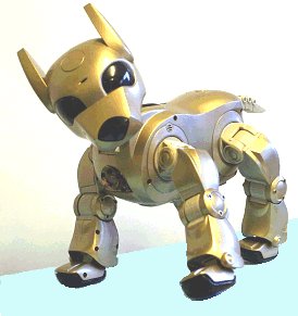
Ask a number of people to describe a robot and most of them will answer they look like a human. Interestingly a robot that looks like a human is probably the most difficult robot to make. It is usually a waste of time and not the most sensible thing to model a robot after a human being. A robot needs to be above all functional and designed with qualities that suit its primary tasks. It depends on the task at hand whether the robot is big, small, is able to move or nailed to the ground. Each and every task means different qualities, form and function; a robot needs to be designed with the task in mind.
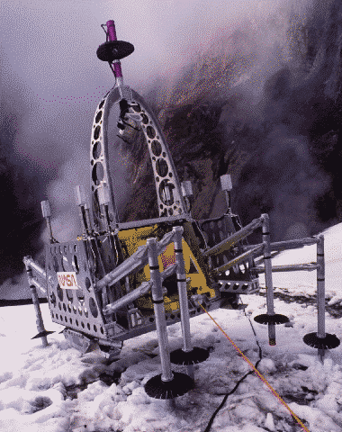
Mobile Robots
Mars Explorer image | Mobile robots are able to move, usually they perform task such as search areas. A prime example is the Mars Explorer, specifically designed to roam the mars surface. Mobile robots are a great help to such collapsed building for survivors Mobile robots are used for task where people cannot go. Either because it is too dangerous of because people cannot reach the area that needs to be searched.
|

Mobile robots can be divided in two categories:
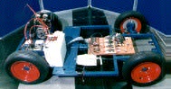
Rolling Robots: Rolling robots have wheels to move around. These are the type of robots that can quickly and easily search move around. However they are only useful in flat areas, rocky terrains give them a hard time. Flat terrains are their territory. | |
|
|
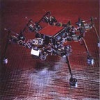
Walking Robots: Robots on legs are usually brought in when the terrain is rocky and difficult to enter with wheels. Robots have a hard time shifting balance and keep them from tumbling. That’s why most robots with have at least 4 of them, usually they have 6 legs or more. Even when they lift one or more legs they still keep their balance. Development of legged robots is often modeled after insects or crawfish.. |
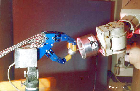
Stationary Robots
Robots are not only used to explore areas or imitate a human being. Most robots perform repeating tasks without ever moving an inch. Most robots are ‘working’ in industry settings. Especially dull and repeating tasks are suitable for robots. A robot never grows tired, it will perform its duty day and night without ever complaining. In case the tasks at hand are done, the robots will be reprogrammed to perform other tasks.. |
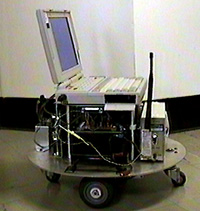
Autonomous Robots
Autonomous robots are self supporting or in other words self contained. In a way they rely on their own ‘brains’. Autonomous robots run a program that give them the opportunity to decide on the action to perform depending on their surroundings. At times these robots even learn new behavior. They start out with a short routine and adapt this routine to be more successful at the task they perform. The most successful routine will be repeated as such their behavior is shaped. Autonomous robots can learn to walk or avoid obstacles they find in their way. Think about a six legged robot, at first the legs move ad random, after a little while the robot adjust its program and performs a pattern which enables it to move in a direction. |
Remote-control Robots
Virtual Robots
Virtual robots don’t exits in real life. Virtual robots are just programs, building blocks of software inside a computer. A virtual robot can simulate a real robot or just perform a repeating task. A special kind of robot is a robot that searches the world wide web. The internet has countless robots crawling from site to site. These WebCrawler’s collect information on websites and send this information to the search engines.
Another popular virtual robot is the chatterbot. These robots simulate conversations with users of the internet. One of the first chatterbots was ELIZA. There are many varieties of chatterbots now, including E.L.V.I.S.
BEAM Robots
BEAM is short for Biology, Electronics, Aesthetics and Mechanics. BEAM robots are made by hobbyists. BEAM robots can be simple and very suitable for starters.
|
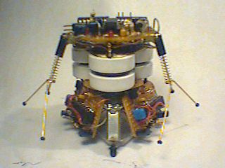
Biology
Robots are often modeled after nature. A lot of BEAM robots look remarkably like insects. Insects are easy to build in mechanical form. Not just the mechanics are in inspiration also the limited behavior can easily be programmed in a limited amount of memory and processing power.
Two basic ways of using effectors are to move the robot around (locomotion) or to move other objects around (manipulation). This distinction divides robotics into two mostly separate categories: mobile robotics (moving) and manipulator robotics (grabbing).
Joints connect parts of manipulators. The most common joint types are:
- rotary (rotation around a fixed axis)
- prismatic (linear movement)
A parallel robot is one whose arms (primary axes) have three concurrent prismatic joints or both prismatic and rotary joints. Degrees of freedom (DOF) means axes of movement. The human arm has seven Degrees of Freedom. A "6 DOF" arm is highly flexible.
Proprioceptive sensors sense the robot's actuators (e.g., shaft encoders, joint angle sensors). Proprioception is one of the most important senses of the human body.
Alternately, robot has been used as the general term for a mechanical man, or an automaton resembling an animal, either real or imaginary. It has come to be applied to many machines which directly replace a human or animal in work or play. In this way, a robot can be seen as a form of biomimicry. Lack of anthropomorphism is perhaps what makes us reluctant to refer to the highly complex modern washer-dryer as a robot. However, in modern understanding, the term implies a degree of autonomy that would exclude many automatic machine tools from being called robots. It is the search for ever more highly autonomous robots which is the major focus of robotics research and which drives much work in artificial intelligence.
The term robot is also often used to refer to sophisticated mechanical devices that are remotely controlled by human beings, such as waldoes and ROVs, even though these devices are not autonomous.
Basic Robots Costituents
Sensors
INFRARED EMITTER DETECTOR
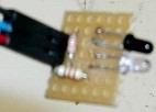
Basic Description
The infrared emitter detector pair act as an eye with a flashlight in the infrared spectrum. The detector (a transistor) detects all ambient infrared light. The emitter (a LED) emits infrared light into an otherwise dark (in the infrared spectrum) room.
Availability and Cost
It is easily available anywhere, very cheap.
Power Requirements
Low, typical LED power requirements.
Tips and Uses
- Don’t bother using this circuit outside, the sun will flood your IR detector and make it useless.
- Certain indoor lighting can also emit IR interference
- Only if you modulate the IR emitter and set the detector to only detect modulated IR can you use this outside. This is commonly done with Sharp IR rangefinders.
- Tweaking is necessary to determine sensitivity of your circuit. Sensitivity will help increase range but also increase ambient interference.
- By using certain resistor values, your IR emitter detector can also detect color, such as for line tracking.
Sonar
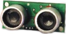
Basic Description
Detects obstacles and can determine object softness/hardness through echolocation.
Typical sonar require ground, power, signal transmit, and signal recieve lines. Transmit a short square wave and the sonar emits a mostly inaudible sound. The sonar keeps the signal recieve line low before the emission and after detecting the return of the emission, high. The distance can be determined by measuring in time how long the recieve line is kept high. FYI, the speed of sound at sea level is 340.29 m/s.
Availability and Cost
Available online for around $20-$30.
Power Requirements
Low, but depends on how active sonar are set to.
Tips and Uses
- Using multiple sonar can be a challenge in that they can trigger each other inadvertently.
- If using multiple sonar, you must trigger each independently and wait for a return.
- This can take a long time if you have 10+ sonar on your robot, so you will have to fiddle with combinations of sonar running simultaneously
- Sonar does not work at very short distances (several inches)
- Remember, sound bounces off of walls and can interfere with later emission readings
DIGITAL COMPASS
Basic Description
The digital compass gives measurements based on Earth's magnetic field for robot navigation. Inside this commonly available MEMS are tiny nano-structures that bend due to electromagnetic fields. When this MEMS experiences any form of EM field, the tiny structures bend by an amount which can be electrically detected. Cheaper digital compasses usually have a resolution of around +/- 5 degrees, but newer and better ones can detect with a better accuracy.
Availability and Cost
It is easily available for $30-$100. It is best to buy them with supporting circuitry included to avoid any interference from bad electrical design.
Power Requirements
Minimal, typical logic only.
Tips and Uses
Keep digital compasses far away from anything that emits EM, such as motors, transformers, inductors, etc.
Large conductive items significantly altar magnetic fields (cars, fridges, steel plates, etc.)
Use this device to help for navigation, such as robot race tracks or navigating a maze
SENSORS - ACCELEROMETER
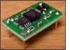
Basic Description
It detects motion, vibration, and angle with respect to gravity.
Inside this commonly available MEMS are tiny nano-structures that bend due to momentum and gravity. When this MEMS experiences any form of acceleration (gravity is a downward acceleration) the tiny structures bend by an amount which can be electrically detected. This means accelerometers can be used to detect and/or control for vibration of a device, acceleration of a robot actuator, or even the angle of the accelerometer with respect to gravity (useful for biped robots).
Note that an accelerometer works on only a single axis, so if you wish to detect on X, Y, and Z planes you need 3 of them. Today many accelerometer MEMS's come with multiple axis for simplicity.
Availability and Cost
They are easily available and very affordable. Usually require support circuitry. Dimension Engineering has a great plug and play dual axis accelerometer which requires no additional support circuitry.
Power Requirements
Minimal, typical logic only.
Tips and Uses
- Placing an accelerometer on a mobile robot that experiences bumps can trigger the accelerometer unintentionally.
- Use a large capacitor to smooth out output over several hundred milliseconds (testing required) to prevent this.
TACTILE BUMP SENSOR CIRCUIT
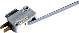
Tactile Bump Sensors are great for collision detection, but the circuit itself also works fine for user buttons and switches as well.
There are many designs possible for bump switches, often depending on the design and goals of the robot itself. But the circuit remains the same. They usually implement a mechanical button to short the circuit, pulling the signal line high or low. An example is the microswitch with a lever attached to increase its range, as shown above.
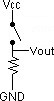
There are several versions below, depending on how you plan to use the circuit and your available switches. For the resistor use a very high value, such as 40kohms.
Tactile Bump Sensor Circuits
Voltage | Voltage | ||
More efficient switch for 3 lead switches |

Tips and Uses
Tactile switches only work if your robot can stop instantaneously (like when moving slowly). There is no point ramming the wall, then the switch saying 'oops, wall here.' This is why more advanced robots often use sonar and IR because it gives a slowing down buffer zone. You will need several to cover the front and/or back of your robot.
Availability and Cost
Micro switches easily available under $1. Use a pop sickle stick lever with it.
Types of Motors
DC Motors
From the start, DC motors seem quite simple. Apply a voltage to both terminals, and it spins. But what if you want to control which direction the motor spins? Correct, you reverse the wires. Now what if you want the motor to spin at half that speed? You would use less voltage. But how would you get a robot to do those things autonomously? How would you know what voltage a motor should get? Why not 50V instead of 12V? What about motor overheating? Operating motors can be much more complicated than you think.
DC motors are non-polarized - meaning that you can reverse voltage without any bad things happening. Typical DC motors are rated from about 6V-12V. The larger ones are often 24V or more. But for the purposes of a robot, you probably will stay in the 6V-12V range. So why do motors operate at different voltages? As we all know (or should), voltage is directly related to motor torque. More voltage, higher the torque. But don't go running your motor at 100V because that’s just not nice. A DC motor is rated at the voltage it is most efficient at running. If you apply too few volts, it just wont work. If you apply too much, it will overheat and the coils will melt. So the general rule is, try to apply as close to the rated voltage of the motor as you can. Also, although a 24V motor might be stronger, do you really want your robot to carry a 24V battery (which is heavier and bigger) around? So a standard recommendation is do not surpass 12V motors unless you really need the torque.
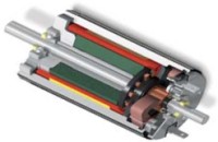
Stepper Motors
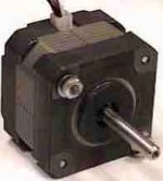
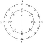
Stepper Motors work under a very similar principle to DC motors, except they have many coils instead of just one. So to operate a stepper motor, one must activate these different coils in particular patterns to generate motor rotation. So stepper motors need to be sent patterned commands to rotate. These commands are sent as high and low logic over several lines, and must be pulsed in a particular order and combination. Steppers are often used because each 'step,' separated by a set step angle, can be counted and used for feedback control. For example, a 10 degree step angle stepper motor would require 36 commands to rotate 360 degrees. However external torque can force movement to a different step, invalidating feedback. Therefore external torque must never exceed the holding torque of a stepper.
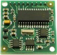
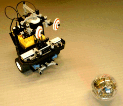
The Robologic stepper motor is a four phase unipolar motor with a step angle of 7.5 degrees. It has 6 wires coming from it in 2 sets of 3. Each set is connected to its own winding. The central pin is the ground pin, and the 2 pins to the left (pin 1) and right (pin 2) are connected to each winding. The arrangement is the same on the second set of pins.
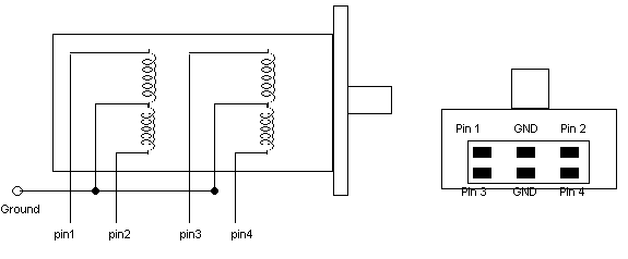
The Robocore can control up to 2 stepper motors using its standard dc motor connections. To follow this example attaches pin 1 and 2 to the Robocore's first motor output and pins 3 and 4 to the second motor output. The two ground pins can be connected together and attached to the batteries negative terminal.
The following sequence steps the motor through one complete cycle.
Step | Pin1 | Pin2 | Pin3 | Pin4 |
1 | ON | OFF | ON | OFF |
2 | ON | OFF | OFF | ON |
3 | OFF | ON | OFF | ON |
4 | OFF | ON | ON | OFF |
1 | ON | OFF | ON | OFF |
The motor can be made to rotate anticlockwise by stepping backwards through the sequence. I.E. Step 4, 3, 2,1,4,3 etc
Notes on Stepper Motors
- Stepper motors can be easily found in any 3.5" disk drive
- Require special stepper motor controllers
- Have a set resolution, higher resolutions mean higher accuracy but lower holding torque
- If torque applied to stepper is greater than holding torque, stepper will lose accurate position measurements
Voltage
- Polarized (current cannot be reversed)
- Typically from 5-12V, but can range to extremes in special application motors
- Higher voltages generally mean more torque, but also require more power
- Steppers can run above or below rated voltage (to meet other design requirements)
- Most efficient at rated voltage
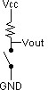
Servo Motors
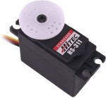
Servos are DC motors with built in gearing and feedback control loop circuitry. And no motor drivers required!
Servos are extremely popular with robot, RC plane, and RC boat builders. Most servo motors can rotate about 90 to 180 degrees. Some rotate through a full 360 degrees or more. However, servos are unable to continually rotate, meaning they can't be used for driving wheels (unless modified), but their precision positioning makes them ideal for robot legs and arms, rack and pinion steering, and sensor scanners to name a few. Since servos are fully self contained, the velocity and angle control loops are very easy to implement, while prices remain very affordable. To use a servo, simply connect the black wire to ground, the red to a 4.8-6V source, and the yellow/white wire to a signal generator (such as from your microcontroller). Vary the square wave pulse width from 1-2ms and your servo is now position/velocity controlled.
Servo Wiring
All servos have three wires:
Black or Brown is for ground.
Red is for power (~4.8-6V).
Yellow, Orange, or White is the signal wire (3-5V).
Servo Voltage (Red and Black/Brown wires)
Servos can operate under a range of voltages. Typical operation is from 4.8V to 6V. There are a few micro sized servos that can operate at less, and now a few Hi-tech servos that operate at much more. The reason for this standard range is because most microcontrollers and RC receivers operate near this voltage. So what voltage should you operate at? Well, unless you have a battery voltage/current/power limitation, you should operate at 6V. This is simply because DC motors have higher torque at higher voltages.
Signal Wire (Yellow/Orange/White wire)
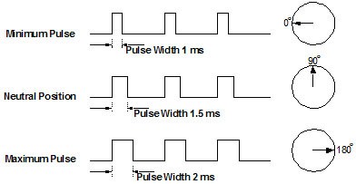
While the black and red wires provide power to the motor, the signal wire is what you use to command the servo. The general concept is to simply send an ordinary logic square wave to your servo at a specific wave length, and your servo goes to a particular angle (or velocity if your servo is modified). The wavelength directly maps to servo angle.
So how do you apply this square wave to your servo? If your robot is remote controlled, your RC receiver will apply the proper square wave for you. If however your robot is running from a microcontroller, you must:
Bring high a digital port
wait between 1-2ms
bring low the same digital port
cycle a few dozen times per second
So how many milliseconds do you keep the port high? It all depends on the servo. You may have to tweak for each individual servo some several microseconds’ difference. The standard time vs angle is represented in this chart:
ROBOT BATTERIES
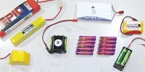
About Batteries
The robots are no longer limited to bulky low power non-rechargeable batteries, and today there is a large assortment to suit your robots' demands. How are batteries rated? With any battery you will see a voltage and a power rating. Battery voltages can be somewhat complicated. When fully recharged, a battery will often be 15% above its voltage rating. When fully discharged, about 15% below its rating. A fully charged battery will also immediately drop below its rating when driving heavy loads, such as a DC motor. To increase battery voltage, wire multiple of them in series. Batteries also cannot supply an infinite current. So expect batteries of different types but equal voltages to have different current outputs. To increase battery current output, wire multiple of them in parallel. This is why batteries often come in assembled packs of smaller cells. So when using a battery, make sure your circuit handles changes in battery voltage. For the power rating you will see something like 1200mAh. mAh means milliamps per hour. So if it is 1200mAh, that means the battery can supply 1.2 amps for one hour or 2.4 amps for 30 minutes or 0.6 amps for two hours.
Alkaline batteries are the most common, easiest to get, and cheapest too. However they are useless, dont buy them. They have low power capacities, are heavy, have trouble supplying large amounts of current in short time periods, and get expensive to constantly replace. The same goes for Zinc-carbon batteries, which suck even more. |

Lead Acid batteries were developed in the late 1800s, and were the first commercially practical batteries. They remain popular because they are easy and inexpensive to manufacture. Rechargeable lead-acid batteries have been available since the 1950s and have become the most widely used type of battery today. |
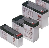
There are three main types of lead acid batteries. Wet Cell (flooded) Gel Cell, and Absorbed Glass Mat (AGM). The Gel Cell and the AGM batteries are specialty batteries that typically cost twice as much as a premium wet cell. However they store very well and do not tend to sulfate or degrade as easily or as easily as wet cell.
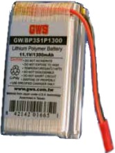
Lithium (Li-ion) is the new standard for portable power. Li-ion batteries have the same high energy capacity as NiMHs, power output rates of NiCads, and weigh about 20%-35% less. They also have zero memory effect problems, meaning you can recharge whenever. Although lithium batteries are the most advanced for portable power, they are also the most expensive. Also, they are made out of totally non-toxic material, making them safe for cute squirrels and pretty trees. What is to be remembered is to, lithium ignites very easily, and forms large quantities of hydrogen when put in contact with water, so don't shoot at it or blow it up or anything of that nature. Also, fire extinguishers are usually water based, so don’t use them on lithium battery fires. |
Interesting points about Robotics
Building robots involves the development of a wide range of skills, including creative thinking, design, mechanics, electronics and programming - all of which are highly valued in industry. Our interest in the subject could lead us into an exciting and fulfilling career at the cutting edge of technology!
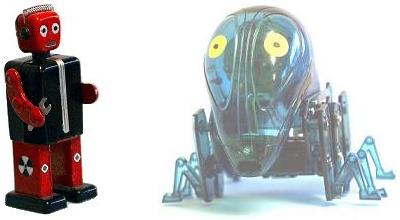
Before the 1960s, robot usually meant a manlike mechanical device (mechanical man or humanoid) capable of performing human tasks or behaving in a human manner. Today robots come in all shapes and sizes, including small robots made of LEGO, and larger wheeled robots that play robot football with a full-size ball.
What many robots have in common is that they perform tasks that are too dull, dirty, delicate or dangerous for people. Usually, we also expect them to be autonomous, that is, to work using their own sensors and intelligence, without the constant need for a human to control them. Looked at this way, a radio controlled aero plane is not a robot, nor are the radio controlled combat robots that appear on television. However, there is no clear dividing line between fully autonomous robots and human-controlled machines. For example, the robots that perform space missions on planets like Mars may get instructions from humans on Earth, but since it can take about ten minutes for messages to get back and forth, the robot has to be autonomous during that time.
Where did the word robot originate?
The word robot was introduced in 1920 in a play by Karel Capek called R.U.R. or Rossum's Universal Robots. Robot comes from the Czech word robota, meaning forced labour or drudgery. In the play, human-like mechanical creatures produced in Rossum's factory are docile slaves. Since they are just machines, the robots are badly treated by humans. One day a misguided scientist gives them emotions, and the robots revolt, kill nearly all humans and take over the world. However, because they are unable to reproduce themselves, the robots are doomed to die.
What are the Laws of Robotics?
The term robotics was coined in the 1940s by science fiction writer Isaac Asimov. In a series of stories and novels, he imagined a world in which mechanical beings were mankind's devoted helpmates. They were constrained to obey what have become known as Asimov's Laws of Robotics:
- A robot may not injure a human being, or, through inaction, allow a human being to come to harm.
- A robot must obey the orders given it by human beings except where such orders would conflict with the First Law.
- A robot must protect its own existence as long as such protection does not conflict with the First or Second Law.
What was the first practical robot?
A prototype industrial robot arm named Unimate (designed by George Devol and Joseph Engelberger) was sold to General Motors in 1959. It plucked hot automobile parts out of a die-casting machine and quenched them in water.
The 1960s and 1970s saw a revolution in manufacturing as robots replaced humans for many repetitive jobs. However, these robots were not intelligent by today’s standards. Usually they were programmed by humans training their movements, and they had very little decision-making capabilities. There are still many robots like this in factories today, but the trend is towards more intelligent general-purpose robots that can do more than just paint a panel or screw in a bolt.
What can't robots do?
It is very difficult to give a robot the ability to perform a wide variety of tasks, move around in cluttered surroundings, recognize objects in the ‘real world’, understand normal speech, and think for itself. These are exciting areas of current research in robotics and artificial intelligence.
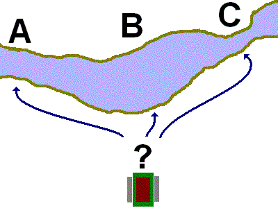
For example, the robot shown here has the problem of deciding where to cross the river. How can it make this decision? How would you do it? Perhaps you have come across a similar situation before. Perhaps you could look it up in a guide book. Perhaps you would reason that B is better than C because the water is likely to be shallower? Perhaps you would choose A, because you tried it before. All these ways of making decisions come very naturally to humans, but they are very difficult to program into robots. |
Another great problem in robotics is getting them to understand language. This is very important in problem-solving. For example, the four cards below have a letter on one side and a number on the other. If a card has a vowel (a, e, i, o, u) on one side then it has an even number on the other. Which cards do you have to turn over to see if this is true? Think about your answer, and then point to a card to turn it over.


Now consider the following cards where the rule is ‘every time I go to Paris I go by plane’. Which cards have to be turned over to test this? Again, think about your answer before turning the card over.


The answer to the first question is that you have to turn over the E to see if it has an even number on the back and you have to turn over the 7 to check that it does not have a vowel on the back. In an experiment, only 12% of people got this second part right (did you?).
The answer to the second question is much easier. Of course you have to turn over the Paris card to check that it has the word plane on the back, but now it’s much more obvious that you have to turn over the train card to make sure it does not have Paris on the back. In the experiment mentioned above, 60% of people got the second part right.
These problems are logically the same, so the experimenters drew the conclusion that the meaning of the symbols is an important part of problem solving. Since robots have very poor language capabilities, their ability to use this kind of reasoning is very limited.
Another of the great problems in robotics is getting them to ‘see’. Although it is easy to put a camera on a robot, it is much more difficult to get the robot to understand what is in an image. Most humans have miraculously good vision. We are able to resolve great ambiguity in scenes. It has proved much more difficult to get robots to understand what is in their universe, and machine vision remains one of the big unsolved problems in robotics research.
There are other problems in robotics that make progress slow. For example, your body is covered with skin, and this contains millions of sensors that allow you to do many fantastically precise things. For example, try typing at a computer with gloves on. The lack of touch feedback will make it very difficult. Also your muscles enable you to have very fine control. Even if you are rather clumsy, you are probably much better at manipulating objects than the average robot. Most people would not let a robot dust their favorite china.
Will robots ever be as good as humans?
Many futurists believe that robots will eventually and inevitably become more capable than humans, but some experts in artificial intelligence assert that machines will never be able to develop the consciousness and emotions needed for reasoning and creativity.
Nonetheless, there are already commercially available robots that can live in our houses and do basic chores for us. Robots are very good at processing certain kinds of information, and they are ideally suited to answering the telephone and being controlled over the Internet.
The International RoboCup Federation has set itself the challenge of having a team of humanoid robot football players beat the human world champions by 2050. Can you image that? It means that robots will have to become as nimble and skilful as Beckham. It will require the invention of many new materials – for example, a human soccer player could be badly hurt if it clashed with a robot made of metal. It will also require an enormous improvement in machine vision. If you play sports such as football, tennis, or even snooker, next time you play think about the huge amount of information that comes through your eyes.
Will robots take over from humans?
This is a popular science fiction theme, and the answer depends on whether robots will ever attain consciousness and emotions. In stories like 2001: A Space Odyssey and Terminator, humans always find a way to outwit intelligent machines that try to take over control. That's fiction, however, and fact is often stranger than fiction!
The suggestion that robots will take over because they might become more intelligent than humans overlooks one critical fact: the people who have power in human societies are usually not the most intelligent in the obvious, intellectual way. They have different kinds of ‘human intelligence’, including the ability to understand other people, and to influence their behavior.
The sensible answer to the question as to whether robots will take over is that they probably won’t in the near future. There are many reasons for this. The first is that the robots of today have puny brains compared to humans, and they do not have the ability to organise in the same way as humans. Our societies are very complex and allow us to achieve many very advanced things. It is unlikely that robots could overtake us in the near future. Even so, it is something that we should keep an eye on, since all scientists have a responsibility not to do things that damage society.
However, for the most part, robots play a very positive role in our societies, and we can expect them to be used in many ways that make life better for us all.
*****
Conclusion
An engineer must have a good practical as well as theoretical knowledge. He must be technically sound as book knowledge is incomplete.
The technical training was an educative as well as interactive. We learned how to make the people learn. Technical lectures presented by the professional technicians related to topics like Robotics, Assembly language were really interesting and healthy to learn the industrial trends. The additional activities such as a session on Aptitude questions and presentations related to the topics provided the chance for overall development of an engineer. It made us learn about the importance of teamwork.
Research and Development center is a true platform to initiate the step towards professionalism in an engineer’s life. I am thankful to all the faculty members and R&D in charge for supporting my work and for providing a right track.
Bibliography
- http://www.societyofrobots.com
- http://www.wikipedia.com
- http://www.epanorma.net
- http://www.electronicsteacher.com
- Embedded Systems – Muhammad Ali Mazidi
46