Buell XB12X Voltage Regulator Connector Check
By ‘Rays’
Overview
The stators and voltage regulators of the pre-2008 Buell XB12X’s appear to have a relatively high failure rate.
While voltage regulators can (and do) fail, it is possible that the ’77 connector’ is at fault and this should be eliminated before replacing the regulator..
The ’77 connector’(77A and 77B) is a 2-pin weather-proof Packard connector located in the wire / connector bundle just forward of the front drive pulley – refer to Figure 1 below:

Figure 1 – XB12X Charging Circuit
The female sockets of connector 77B can be slightly deformed to form a poor electrical connection. This poor connection can then begin to arc and add carbon deposits to the connection making a poor connection worse. This can result in a connection effectively insulated by carbon or in a worst case scenario, the resistive connection will overheat to the point of melting the connector housing – refer to Figure 2 for an example of a melted connector housing 1.
The female socket highlighted in Figure 2 is also a perfect example of a deformed spring contact.
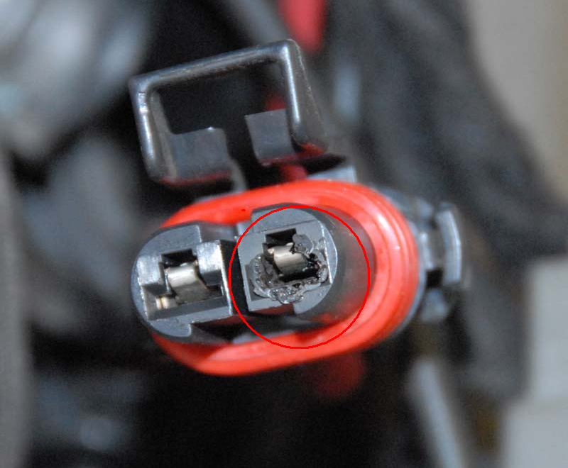
Figure 2 – Melted ’77 Connector’ Housing
The snug fit of the male pin depends on the both the shape of the female socket (particularly where indicated by item ‘C’ in Figure 8) and the tension of the spring contact (item ‘B’ in Figure 8). The correct fit of this connection in cross-section is illustrated in Figure 3 below:
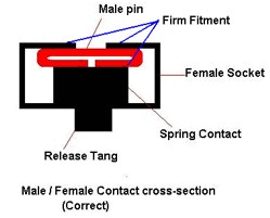
Figure 3 – Correct Connector Cross-Section
When the socket is deformed slightly (I assume this could be as a result of plugging the male in at an angle) and the spring contact is also slightly compressed, the cross-section will look more like the shape indicated in Figure 4.
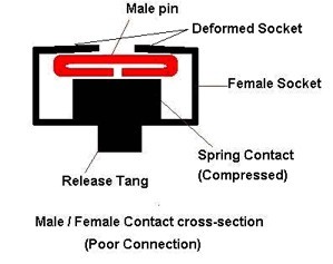
Figure 4 – Incorrect Connector Cross-Section
Checking the Connector Pins and Sockets
WARNING: The connectors, pins and sockets that are the subject of this maintenance activity are relatively frail and easily damaged. Any physical actions should be undertaken gently and carefully.
Step 1. Disconnect the main battery – the connector we are dealing with is wired directly to the battery (via the 30A Battery Fuse). To avoid any accidental shorting or disconnecting / connecting of the regulator while ‘live’ I would always isolate the main battery before attempting this check.
Step 2. Remove the front pulley cover (on a XB12X that needs the chin spoiler to be either removed or partially removed to allow access to the lower Torx screw on the cover).
Step 3. locate connector 77 which is a large 2-pin connector that is positioned against the plastic guard located in front of the pulley (see item 1 in figure 5 below). You may need to clip some zip-ties in order to have the connector removed to the point where it can be disconnected and re-connected while keeping the male and female connectors ‘square’ to each other.
Note: When reconnecting this connector, it is important not to insert the male pins into the female sockets at an angle to avoid spreading the female socket.

Figure 5
Step 4. Disconnect connector 77A and 77B. To do this gently lift the plastic connector latch and pull the two connectors apart (see figure 6 below for location of latch).
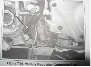
Figure 6
Step 5. On the rear of the loom side connector (77B) locate the plastic clip that holds the red and black wires where they exit and remove this clip from the connector housing and place it somewhere where you won’t stand on it.
Step 6. These Connectors are manufactured by Packard and are of the rear-entry, front release type. The release tang is released via a small square entry hole – see item ‘D’ in figure 7 below.

Figure 7
Step 6 (cont). The release tang (item A in figure 8) is released by placing a small instrument screwdriver (or similar) in the access hole (item D in Figure 7) and inserting until the tang is felt. While placing gentle rearwards pressure on the female socket by pulling lightly on the wire, push the screwdriver a little more until the tang is deflected enough to release the socket. When this point is reached the socket will release very easily (unless the contact has overheated and there is obvious melting of the housing as shown in Figure 2).
If the housing has been overheated to the point of melting then more drastic action (such as cutting the housing apart) may be required – this will need to be dealt with on a case by case basis and is outside the scope of this cleaning procedure.
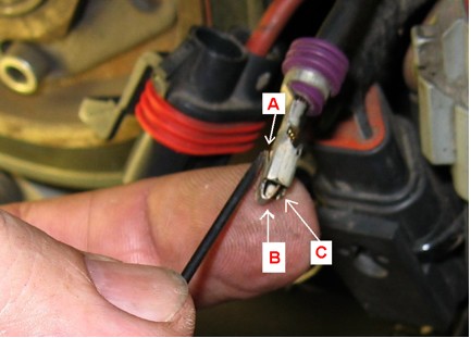
Figure 8
Note: Only depress the tang as much is required to unlock it, this tang can be pushed absolutely flat or even past that point and inside the socket if you push hard enough but doing so will reduce the life of the tang as it will break off completely without too many bending actions.
Once the socket is removed, bend the tang up again slightly so it will be able to lock back into place when re-inserted. This does not have to be any more than is indicated in Figure 8.
Warning: Only remove one socket / pin at a time as these connectors are polarised and if you manage to get the positive and negative wires crossed you will almost certainly destroy the regulator and probably a lot more of the electronics. If you insist on living dangerously then mark the positive side of each connector (see white dot on the positive side of the connector in the background of the photo in Figure 8). On the regulator side you will also need to mark the positive wire as they are both black and very easily mixed up.
Step 7. What is required now is to clean the socket of any carbon build-up – I used a Scotch pad and toothbrush with Methylated spirits (contact cleaner will also work) and to reform the socket to ensure a firm fit of the male pin.
This can be easily done by using a pair of clean pliers to gently bend the open side of the socket so the edges are flat as per the Cross-Section drawing in Figure 3.
The other part to ‘form’ is the spring contact (item B, Figure 8). I used a metal scriber to bend this gently up towards the open side of the female contact.
The correct shape of the female socket is such that the male pin is a firm fit. The male pin has to deflect the female spring contact on one side and have maximum contact with the parallel edges of the open side of the female socket.
Please refer to the shape of the spring contacts in Figure 2 – the male pin should have to deflect this contact when inserted.
I would recommend removing one female and one male socket / pin pair at a time so you can fit them together outside of the connector housings to get a good ‘feel’ for the fitment.
Warning: To reduce the possibility of a major mistake when doing this, it is extremely important that the battery is disconnected and to be doubly sure to work on the positive and negative side separately.
Step 8. When the male and female pin and sockets are clean and re-shaped all that remains is to make sure the locating tang is repositioned as described in Step 6 and to re-insert in the connector housing. A distinct ‘click’ will be evident when the socket is locked in position.
Step 9. Repeat the removal and cleaning for the other male / female pin / socket pair.
Step 10. Refit the plastic cable clips removed in step 5 to both housings and press the two halves of77A and 77B together while carefully keeping them inline as they are pressed together.
Step 11. Put everything removed in Step 1 and 2 back together in reverse order and the job is complete.
Acknowledgements.
1. Picture posted by ‘Doncastro’ on BadweatherBikers.com - 2008.
Appendix A.
Updated replacement regulator – part number Y1302.02A8.
This regulator is supplied with Voltage regulator Connector Service kit Y1312.02A8.
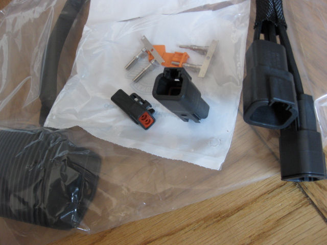
Figure 9.
This updated ‘77’ connector appears to be a Deutsch 2 pin DTP plug and socket.
Ver 1.1
09-May-2009