
G2 GSM CONTROLLER V2.0 COMPLETE MANUAL
200 User Caller ID Access Control - Event Log (1015) - GSM Audio Intercom System
Introduction...
- The G2 GSM controller enables control of virtually any device via authorised telephones & management from Authorised Administrator mobile phones
- G2 has an inbuilt event log which stores input & output activity and is accessible by SMS or PC
- 2 configurable alrm inputs allow SMS text alerts to be easily sent to selected Authorised mobile phones
- 2 configurable outputs enable various combinations of switching to enable any device to be switched from gates, barriers, magnetic locks. lights, heating etc.
- G2 GSM intercom function enables 2 way wireless intercom communication from the GSM call point to land-line or mobile phones of the User's choice
Click the following Heading links to view that section of the guide
- QUICK START GUIDE (start here for the most basic set up)
- a) Make the Minimum Connections
- b) Insert any Activated SIM card
- c) Power Up & wait for the Blue LED to start flashing
- d) Set a User Phone Number to Test...
- e) Call G2 to test the output...
- GUIDE TO SMS TEXT MESSAGE PROGRAMMING
- a) Benefits of G2 SMS Text Based Programming
- b) SMS Text Based Programming Explained (please read carefully)
- G2 TECHNICAL OVERVIEW
- a) Hardware Description & Connection Diagram
- b) Hardware Features
- c) Technical Specifications & Values
- GUIDE TO PC PROGRAMMING VIA USB
- a) PC Programming using any Windows PC
- CALLER ID DEVICE CONTROL [CLIP] mobile phone dialing in to switch G2
- a) Disable the CLIP Feature (CLPEN=0)
- b) * Enable CLIP 'Authorised Callers Only - 200 Users' (CLPEN=1) (default setting)
- c) Enable CLIP 'Any Caller Mode' - Unlimited Users (CLPEN=2)
- d) Choose which Output to Switch (CLPOU=1)
- e) Link the CLIP feature to an actived Input in order to enable (CLPI=0)
- f) Retrieve the 200 User List in Full or in Parts to Delete or Add New Users (PCLP=xy,xx)
- g) Add or delete Authorised Callers (CLP1 - CLP200)
- SET UP TO 5 AUTHORISED ADMINISTRATORS FOR PROGRAMMING & ALERTS
- a) Add or delete Authorised Administrator Mobile Numbers (TN1 - TN5)
- b) Set up Active Authorised Administrator Mobile Numbers (SL)
- c) Link Events from Inputs or Preset Events to Authorised Administrators (LN1 - LN6)
- CALLER ID EVENT LOG
- a) Set up the Self Updating Clock (UDC)
- b) Change the Event Log Buffer from Auto Clear to Manual Clear & Send Alert at 900 events (ALC)
- c) Request Event Log by SMS Text Message (PLOG)
- d) Set the default amount of Events to receive by SMS Text Message (LOGN)
- e) Request how many Events are in the Current Event Log (PLOG=?)
- f) Request Event Logs between a set range of Total Events (PLOG=xy,xx)
- g) How to find the most Recent Events
- h) After Retrieving & Saving the Event Log to your PC, Erase completely by SMS Text (LCLR)
- OUTPUTS FOR SWITCHING DEVICES
- a) Request Current Output Switch Status Pulse, Latch, Timed, 1st call ON / 2nd OFF (POS)
- b) Request Current Output State (PORC)
- c) Change Output Switching Status Pulse, Latch, Timed, 1st call ON / 2nd call OFF (OS1 & OS2)
- d) Change an Output Contact between Open [going closed] or Closed [going open] (OP1 & OP2)
- e) Make an Output Directly Switch when an Input 1 is Activated (OD1) ie: press to exit input
- f) Make an Output Directly Switch when an Input 2 is Activated (OD2) ie: siren/flashing beacon
- g) Make an Output Directly Switch when a GSM Network Error occurs (OD3)
- h) Make an Output Directly Switch when an Unauthorised Caller calls G2 (OD4)
- i) Control an Output by SMS Text Message (ORC)
- SET UP INPUTS FOR SMS TEXT ALERTS or GSM INTERCOM CALL BUTTONS
- a) Change how inputs trigger & whether an SMS text is sent to notify 'input restored' (IN1 & IN2)
- b) Change the time delay before SMS text alerts are sent after inputs activated (ID1 & ID2)
- c) Request the current Device labels for the SMS Text Alerts (P#)
- d) Change the label printed on the SMS text alert sent related to Device (#0LOCATION)
- e) Change the label printed on the SMS text alert sent related to Input 1 (#1INPUT 1)
- f) Change the label printed on the SMS text alert sent related to Input 2 (#2INPUT 2)
- GSM INTERCOM SET UP
- a) Enable the Inputs to be used as GSM intercom Call Buttons (WMOD)
- b) Set Up the Numbers called by Call Button 1 (PDEA)
- c) Set Up the delay timer before dialing the next number (RTNA)
- d) Set Up the Numbers called by Call Button 2 (PDEB)
- e) Set Up the delay timer before dialing the next number (RTNB)
- f) Door Release
- MISCELLANEOUS PARAMETERS (SIM, Device & GSM Intercom)
- a) General Settings (defaults shown)
- b) SIM Card / Mobile Network Settings (defaults shown)
- c) Device Reset (defaults shown)
- SMS TEXT PRINT COMMANDS (automatically prompt G2 for current settings)
- a) Receive all Current Parameters Set (PALL)
- b) Receive all Current Caller ID Control Settings, Authorised Callers & Vacant Slots (PCLP)
- c) Receive all Authorised Administrator Mobile Numbers and/or Vacant Number Slots (PTN)
- d) Receive the Security Level ie: Which Administrators are allowed to program G2 (PSL)
- e) Receive which alerts are 'Linked' to which Authorised Administrators (PLN)
- f) Receive Input configuration ie: How long they must be active before alerts are sent (PID)
- g) Receive Output configuration ie: How outputs are set to switch; pulse, latch, timed (POS)
- h) Receive Current Output States ie: Are they active or not (PORC)
- i) Receive Direct Output configuration ie: How outputs switch on Input / Event activity (POD)
- j) Receive programmed labels for the device Name / Location & Inputs (P#)
- k) Receive the Current Settings of the Miscellaneous Parameters (PPA)
- l) Receive the remaining SIM card credit (PCC1)
- m) Receive the Current Settings for the GSM Intercom Feature - BUTTON 1 (PDEA)
- n) Receive the Current Settings for the GSM Intercom Feature - BUTTON 2 (PDEB)
- LED DISPLAY
- 1. BLUE GSM Network Signal Strength (1 Flash = Low Signal / 5 Flashes = Maximum Signal)
- 2. RED Device / Connection / Network Fault
- 3. YELLOW GSM Network (1 Flash/sec. = Registering & 1 Flash per 5 sec. = On Network)
- TROUBLESHOOTING
- a) Device won’t connect to the GSM network
- b) General audio interference during intercom calls
- c) Whistling or interference all the time or during a call
- d) Device won’t respond and blue LED is solid
- e) SMS Programming won't work
- f) Voicemail cuts in before my intercom call transfers to the second number
- g) Speaker Level is too low / high
- h) Red LED is solid
- i) Red LED is Flashing
- j) If your issue is not listed here
QUICK START GUIDE (start here for the most basic set up)
QUICK
For those that want the most simple of features, the device is set up with default settings that more than likely suit your task. Get up & running within minutes.
Add additional features by following the manual to set other Security features & Authorised Users.
a) Make the Minimum Connections
Connect an input power supply 12-24V AC or DC. Connect the device to be controlled to the output 1 switch. It is a voltage free open contact. It can also be configured to be a closed switch going open on activation by moving the blue jumper next to the relay to the opposite pins.
If you aren't using the GSM intercom, USB for PC software or Weigand Output, just ignore those connections.
b) Insert any Activated SIM card
Insert the SIM card gold contacts down with the cut off corner to the top RHS as shown on the lid diagram.
If using an 02 or Orange UK PAYG SIM card, send this text message first before any other: ;+SPO=10;
c) Power Up & wait for the Blue LED to start flashing
Switch on the power supply. The LED's flash in a particular way while starting up and then change when G2 is ready for use. Check that the LED's conform to the following table:
LED | STATUS (FLASHING) |
BLUE (START UP) | SOLID |
YELLOW (START UP) | FLASHES ONCE PER SECOND |
RED (START UP) | FLASHES WHILE READING SIM CARD ONLY |
BLUE (READY) | FLASHES TO INDICATE SIGNAL (1 LOW - 5 MAX.) |
YELLOW (READY) | FLASHES ONCE PER 5 SECONDS |
RED (READY) | OFF |
d) Set a User Phone Number to Test...
The device is set by default to switch Relay Output 1 & by Authorised Users only so you must first add one.
IMPORTANT: If using an 02 UK PAYT SIM card, send this text message first before any other: ;+SPO=10;
Now Send this SMS text message...
;+CLP1=XXXXXXXXXXX; where XXXXXXXXXXX = the authorised User phone number
e) Call G2 to test the Caller ID output...
Dial the number of the SIM card in G2 from the number just programmed above. It will recognise the number and switch the output. You will here a tone and a click.
f) Set an Intercom Call button to Test...
You can set up to 5 number that the intercom will call.
Now Send this SMS text message...
;+ATN1=XXXXXXXXXXX; where XXXXXXXXXXX = the User phone number to be called
To set more numbers...
;+ATN1=XXXXXXXXXXX;ATN2=XXXXXXXXXXX;ATN3=XXXXXXXXXXX; and so on ..... where XXXXXXXXXXX = the User phone numbers to be called in this order
GUIDE TO SMS TEXT MESSAGE PROGRAMMING
The unit can be completely controlled & managed by SMS Text Messages. This is the most convenient method for End Users and can be carried out from anywhere in the world instantly.
a) Benefits of G2 SMS Text Based Programming
- Request current settings with unique SMS text 'Printout Requests' before making any changes
- Choose to receive or omit a confirmation reply message from G2 (add + see below)
- Send multiple commands per message up to a max. of 160 characters (seperated by ; see below)
- Instantly applied to the G2 & stores a text record of sent & received information on your mobile
- Up to 1000 User Event logs at your fingertips from anywhere in the world without a PC
b) SMS Text Based Programming Explained (please read carefully)
- The G2 device is programmed by a set of individual Parameters & Values...
- These instructions apply to SMS text sent from mobile phones or via PC using optional software
- ---------------------------------------------------------------------------------------------------------------
- Every SMS Text Command sent must start & end with ; and each parameter & value separated by =
- Multiple commands can be connected together as shown above seperated by ;
- To receive a confirmation reply by SMS Text you must put a + after only the very first ; as shown
- Ie: ;+ATN1=07796178987;ATN2=02074156786;RTNA=15;
G2 TECHNICAL OVERVIEW
Technical details about the hardware, terminal layouts, technical capability & requirements.
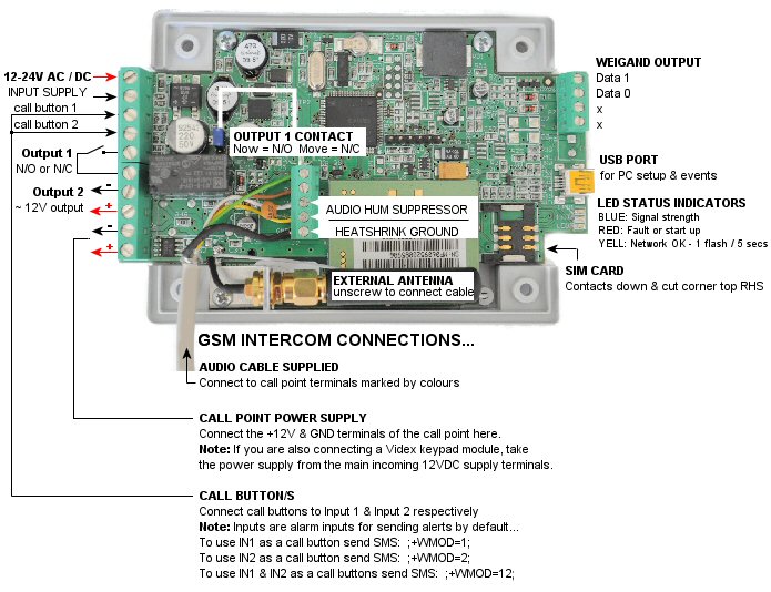
a) Hardware Description & Connection Diagram
- 12-24V AC or DC INPUT SUPPLY (minimum 500Ma): This powers the device
- Input 1: Link to GND & an SMS alert will be sent to Authorised User 1 or Call button 1
- Input 2: Link to GND & an SMS alert will be sent to Authorised User 1 or Call button 2
- Output 1 (relay): Voltage free open contact used to switch most devices
- Output 1 (relay): As Above - Both terminals are used to switch your device
- Output 2 (GND): Auxiliary output for switching low power devices such as relays
- Output 2 (+12V): Auxiliary output for switching low power devices such as relays
- *GND: for powering a GSM intercom call point
- +12VDC: for powering a GSM intercom call point
- Audio Cable Connections: Audio terminals to the GSM intercom call point
- External GSM Antenna: Connect an optional antenna on 3m cable
- LED Status Display: See the start up, GSM signal strength & Network activity
- USB Port: PC programming & event log retrieval by PC
- Weigand Output: For connection to a Weigand based Access System for mobile phone access

b) Hardware Features
HARDWARE FEATURES | VALUE |
N/O & N/C Relay Output 240VAC 5A contact | 1 |
Alarm Sensor Inputs | 2 |
GSM Intercom Call Buttons | 2 |
12VDC (open collector) Alarm Output | 1 |
12V DC Power Supply Input | Y |
12/24V AC/DC Power Supply Input | Y |
Alarm SMS Text Alerts | 2 |
Authorised Administrator Mobile Numbers | 5 |
CLIP (Caller ID) Authorised Caller Numbers | 200 |
'Any Caller Mode' Caller Numbers | Unlimited |
Event log buffer | 1000 |
c) Technical Specifications & Values
GUIDE TO PC PROGRAMMING VIA USB
The unit can be programmed by PC using optional software available for download here
a) PC Programming using any Windows PC
- You will need to plug the unit into your PC using a USB to mini USB cable
- You must first install the Driver for the GSM Controller mini-USB port DOWNLOAD THE USB DRIVER
- Check which COM port your GSM Controller is connected to in your PC Control Panel (Start > Control Panel > Performance & Maintenance > System > Hardware > Device Manager > Ports)
- PC Programming Software available from your Supplier MORE INFO HERE
CALLER ID DEVICE CONTROL [CLIP] mobile phone dialing in to switch G2
Set up G2 to control your gate, barrier, heating or whatever else you choose to control. The feature can be configured in 2 work modes; 'Authorised Caller' or 'Any Caller'. Authorised Caller is the default setting.
a) Disable the CLIP Feature (CLPEN=0)
To temporarily disable the CLIP feature, send text: ;+CLPEN=0;
- This will not affect any Authorised Callers already set up
b) * Enable CLIP 'Authorised Callers Only - 200 Users' (CLPEN=1) (default setting)
To enable the 'Authorised User List', send text: ;+CLPEN=1;
- Only Users on the list can switch the device.
c) Enable CLIP 'Any Caller Mode' - Unlimited Users (CLPEN=2)
To enable 'Any Caller Mode' , send text: ;+CLPEN=2;
- This mode is less secure as any incoming call will switch the device.
d) Choose which Output to Switch (CLPOU=1)
The CLIP feature can be used with only one Output. G2 V.2 will have dual output switching on separate numbers.
To enable output 1, send text: ;+CLPOU=1;
To enable output 2, send text: ;+CLPOU=2;
e) Link the CLIP feature to an actived Input in order to enable (CLPI=0)
The CLIP feature can be used in conjunction with an Input which means the Input must be active before teh CLIP feature can operate. An example is a ground induction loop that must be driven onto before the barrier/gate or device can be activated. This prevents remote control of the device unless another physical parameter is met.
i.) If Input 1 is to be used to arm the CLIP feature, send SMS text: ;+CLPI=1; (note: ;LN1=0;)
- The device can only be switched by the CLIP feature if Input 1 is active
ii.) If Input 2 is to be used to arm the CLIP feature, send SMS text: ;+CLPI=2; (note: ;LN2=0;)
- The device can only be switched by the CLIP feature if Input 1 is active
iii.) To enable the CLIP feature without activating an Input, send SMS text: ;+CLPI=0;
- The device can be switched by the CLIP feature as normal without any Input connection
f) Retrieve the 200 User List in Full or in Parts to Delete or Add New Users (PCLP=xy,xx)
You can retrieve all or some of the Authorised Callers by sending SMS text message: ;PCLP=xy,xx; (where xy,xx = the range between User positions in the device memory.
The device will reply with your selected range of User slots to show the vacant and occupied slots.
Tip: Allocate sections of the CLIP User memory to groups of Users for quick retrieval by SMS text message.
example: CLP1 - CLP50 (Internal Staff) CLP51 , CLP100 (Drivers) CLP101 - CLP150 (Visitors) etc...
Tip: If you want to find the List position of an 'existing Driver' in order to delete the phone number, or just 'add a new Driver' to the list, you request only that section of the User List with SMS text message: ;PCLP=51,100;
- only that section will be returned with currently occupied positions and any free positions.
To Edit the User List:
1. Select 'Forward Message' in your mobile phone text options and choose the SIm card number of G2
2. Edit the message received to either 'add or delete' the Users as required
3. Send the edited message back to the device
g) Add or delete Authorised Callers (CLP1 - CLP200)
To add 'Authorised Callers' to the 200 User list, you must enter the phone number in a vacant slot in the list. By SMS Text message, you can request individual slots or a range of any 2 numbers between 1 - 200.
ie: Retrieve the first 20 slots from the list, send text: ;PCLP=1,20;
ie: Retrieve more slots from the list, send text: ;PCLP=21,50;
... and so on
Depending on how many User slots you request, you will receive 1 or multiple replies including the current CLIP setup as above and the Occupied & Vacant for the selected range.
Example:
;PCLP=1,3;
- You will receive a reply as follows
;CLPEN=1;CLPOU=1;CLP1=;CLP2=;CLP3=;
1. Select 'Forward Message' in your mobile phone text options.
2. Edit the message as required by adding the numbers you want to add. Note the + symbol. This means a reply confirmation will be returned. Omit the + to disable the reply:
;+CLPEN=1;CLPOU=1;CLP1=077965124589;CLP2=02074561254;CLP3=02074561253;
3. Send the message back to the SIM card in the device to update the settings.
h) To delete Authorised Users
Remove the number between the = and ; symbols that you want to delete. Note the + symbol. This means a reply confirmation will be returned. Omit the + to disable the reply:
;+CLPEN=1;CLPOU=1;CLP1=077965124589;CLP2=;CLP3=;
i) Automatic Re-CLIP function (auto close pulse for gates not set to auto close)
About: After a CLIP command (caller ID incoming call) is received, G2 switches the output as set.
If the auto re-clip feature is set, G2 looks at the input number set in CLPRI and will automatically make a second pulse of the same output if the input hasn't been triggered within a set time to indicate a photocell has been passed.
The time window for this function is set using CLPRT. Ie: If the input remains active for longer than this time, the G2 will not automatically repulse the output.
Why?
If an automatic gate is set as 'press to open' & 'press to close', this function acts as an automatic second pulse to close the gate without actually having to press anything. It checks the input to make sure it's safe first. Your safety beam contact would be wired through the G2 input so G2 can check if they are obstructed or not before sending the close pulse. If the featre times out, G2 does not switch.
Also useful in case an garage or gate was opened remotely by mobile phone inadvertently. The G2 will check the input is not active (ie saftey beam broken) and it will pulse to close making it very secure.
;CLRPI=X; Input number for auto reclip function (X = the input number ie: 1 or 2)
;CLPRT=XX; Time window (XX = the time frame in seconds within which the G2 will check the input)
SET UP TO 5 AUTHORISED ADMINISTRATORS FOR PROGRAMMING & ALERTS
Authorised Administrators are 'authorised' to program the device by SMS text & also receive SMS text alerts for various event as set by parameter LN. By 'linking' events (LN1 - LN5) to Authorised Administrators, you can select certain Administrators to receive alerts for some or all events.
a) Add or delete Authorised Administrator Mobile Numbers (TN1 - TN5)
Send this SMS text message to receive a list of Current Authorised Administrators: ;PTN;
- You will receive a reply: ;TN1=;TN2=;TN3=;TN4=;TN5=;
TN1 | 07798765140 | Authorised Administrator 1 (default for all SMS alerts) |
TN2 | xxxxxxxxxxx | Authorised Administrator 2 |
TN3 | xxxxxxxxxxx | Authorised Administrator 3 |
TN4 | xxxxxxxxxxx | Authorised Administrator 4 |
TN5 | xxxxxxxxxxx | Authorised Administrator 5 |
To change the above example setting, send: ;TN1=07798765140;TN2=;TN3=;TN4=;TN5=;
b) Set up Active Authorised Administrator Mobile Numbers (SL)
You can allow any mobile number to program G2 by SMS text by leaving it as the default setting. If you want to restrict programming to a limited number of Administrators, send this SMS text message to receive the currently set Security Level: ;PSL;
- You will receive a reply: ;SL=0;
Reply to the message and set one of the following parameters to allow numbers in your Authorised Administrator list to program the G2 exclusively.
Security Level SMS Text Commands | Description |
;+SL=0; | Any number will be accepted (DEFAULT) |
;+SL=1; | Only Authorised Administrator TN1 is allowed |
;+SL=2; | Only Authorised Administrators TN1 & TN2 are allowed |
;+SL=3; | Only Authorised Administrators TN1 - TN3 are allowed |
;+SL=4; | Only Authorised Administrators TN1 - TN4 are allowed |
;+SL=5; | Only Authorised Administrators TN1 - TN5 are allowed |
To change the setting, send: ;+SL=X; Where 'X' = your chosen security level as detailed above
c) Link Events from Inputs or Preset Events to Authorised Administrators (LN1 - LN6)
Linking events to Authorised Administrators enables you to direct alerts to the most suitable people.
You can add multiple Administrators per alert by adding just the number of the Administrator 1 - 5 after the LN command for each alert.
Alerts SMS Text Commands (x = Auth. Admin.1 - 5) | Description |
;+LN1=xxxxx; | Activity on Input 1 |
;+LN2=xxxxx; | Activity on Input 2 |
;+LN3=xxxxx; | Periodic Test Alert |
;+LN4=xxxxx; | Low Credit Alert |
;+LN5=xxxxx; | NAC (Non-Authorised Call or SMS text) |
;+LN6=xxxxx; | Event Log Buffer Full (1000 events) |
To change the setting, send: ;+LNx=y;
Where 'x' = The 'Alert Link' number as above (LN1 - LN6)
Where 'y' = The 'Authorised Administrator' number/s as detailed above (TN1 - TN5)
Note: You can add more than 1 Adminsitrator: Just add the numbers ie: ;+LN1=123;
CALLER ID EVENT LOG
Calls made to the SIM card in G2 are Events and are logged by Date, Time, Phone Number, Output & Authorised / Non-Authorisd Status. Activity on the Inputs is also logged by Active & Restored Status. Up to 1000 events are logged.
The Event Log can be requested in various ways by both SMS Text Message & PC via the onboard mini USB port to ensure quick and simple retrieval of Events within the entire Log.
a) Set up the Self Updating Clock (UDC)
G2 will send itself an SMS text message after it loses power to refresh the clock with the Network Operators Clock.
To set the feature, enter the mobile number of the SIM card you have put into G2 by sending this SMS text: ;+UDC=XXXXXXXXXXX;
b) Change the Event Log Buffer from Auto Clear to Manual Clear & Send Alert at 900 events (ALC)
The Event Log is full at 1000 Events. By default, G2 will automatically clear the event log when it is full. You can change this for 'Manual Log Clear' by sending an SMS text message.
;+ALC=0; (Event Log will send an SMS text alert when 900 Events are in the device - User must clear*) ;+ALC=1; (Event Log will automatically clear after 1000 Events are in the device) DEFAULT SETTING
*With Automatic Log Clear set, you can still request the event log at any time and retrieve log events. If you retreive log events regularly and save them, you can use the manual Log clear at any time by sending SMS text message: ;LCLR;
The Event Log will then start from 0001 again.
c) Request Event Log by SMS Text Message (PLOG)
To return the Events by either SMS Text Message, first you should set the default amounts of events to be returned. Note by SMS text message, each log is sent in 1 message so 5 events will send 5 messages.
The default amount of SMS logs is 5.
1. To request the events, send this SMS text: ;PLOG;
- The G2 will only send you the most recent 5 events.
To clear the device and start a fresh event log send SMS: ;LCLR;
d) Set the default amount of Events to receive by SMS Text Message (LOGN)
Note: You will receive the most recent events in individual SMS text messages
The default amount of events sent is 5.
To change it:
1. First send this command ;LOGN=10;
2. Then send this command to get the events ;PLOG;
- 10 events will be returned.
e) Request how many Events are in the Current Event Log (PLOG=?)
To return how many events are in the current Log memory, send this SMS text message ;PLOG=?;
f) Request Event Logs between a set range of Total Events (PLOG=xy,xx)
Send this SMS text message with a range of event logs: ;PLOG=xy,xx; (where 'xy,xx' = the range of event log numbers)
g) How to find the most Recent Events
If you want to know the most recent events, first you need to check how many Events are currently in the device. Send the SMS text message: ;PLOG=?;
- The reply will be: Num. of LOG Entries:95 (95 is an example only)
From this point you know you have '95' events in memory so send this SMS text message to retrieve the most recent 5 events: ;PLOG=90,95;
h) After Retrieving & Saving the Event Log to your PC, Erase completely by SMS Text (LCLR)
Send this SMS text message to clear all events and start a fresh Event Log: ;LCLR;
OUTPUTS FOR SWITCHING DEVICES
G2 has 2 outputs which switch in the same way however the outputs are completely different. Output 1 is a voltage free contact which is set open by default. It closes when it is activated and makes a voltage free connection between the 2 terminals marked 'relay'.
Output 2 is different in the sense that it is not voltage free when it is activated. It supplies 300mA max. from the 2 terminals marked Out 2 GND & Out 2 +12VDC. It supplies a voltage near to 12VDC depending on your input supply voltage and is designed to power low consumption 12VDC devices such as relays.
a) Request Current Output Switch Status Pulse, Latch, Timed, 1st call ON / 2nd OFF (POS)
Send this SMS text message to receive the current configuration of each output: ;POS;
- You will receive a reply like this: ;OS1=5;OS2=5;
b) Request Current Output State (PORC)
Send this SMS text message to receive the current state of each output: ;PORC;
- You will receive a reply like this: ;Output 1=OFF;Output 2=OFF;
c) Change Output Switching Status Pulse, Latch, Timed, 1st call ON / 2nd call OFF (OS1 & OS2)
By default, both outputs are set 'Normally Open' & will pulse closed for 5 seconds. Both outputs can be configured to switch in various ways to suit multiple applications.
Output Setup SMS Commands (x = output number 1 or 2) | Description | |
;+OSx=0; | Output Disabled | |
;+OSx=1; | Output Latching (ON by call / OFF by SMS text) | |
;+OSxR=1; |
| |
;+OSx=2; | Output Pulse for 2 seconds | |
;+OSx=xyz; | Output timed pulse (xyz = any time period in seconds) |
d) Change an Output Contact between Open [going closed] or Closed [going open] (OP1 & OP2)
The default setting for both outputs is N/O or 'Normally Open' [Open switch going closed].[1]
i) To make an Open switch close when activated (DEFAULT)
To change Output 1, send SMS text message: ;+OP1=0;
To change Output 2, send SMS text message: ;+OP2=0;
i) To make a Closed switch open when activated
To change Output 1, send SMS text message: ;+OP1=1;
To change Output 2, send SMS text message: ;+OP2=1;
e) Make an Output Directly Switch when an Input 1 is Activated (OD1) ie: press to exit input
Outputs can be set to switch immediately as inputs are triggered. This is useful for 'press to exit'.
- To switch Output 1 when Input 1 is activated, send SMS text message: ;+OD1=1;
- To switch Output 2 when Input 1 is activated, send SMS text message: ;+OD1=2;
To see how to configure Inputs see the Inputs section of this manual.
f) Make an Output Directly Switch when an Input 2 is Activated (OD2) ie: siren/flashing beacon
Outputs can be set to switch immediately as inputs are triggered. This is useful for 'alarm notification'.
- To switch Output 1 when Input 2 is activated, send SMS text message: ;+OD2=1;
- To switch Output 2 when Input 2 is activated, send SMS text message: ;+OD2=2;
To see how to configure Inputs see the Inputs section of this manual.
g) Make an Output Directly Switch when a GSM Network Error occurs (OD3)
Outputs can be set to switch immediately if a Network Fault occurs.
- To switch Output 1 when a Network Fault occurs, send SMS text message: ;+OD3=1;
- To switch Output 2 when a Network Fault occurs, send SMS text message: ;+OD3=2;
To see how to also send an SMS text Alert to Authorised Administrators see the section of this manual.
h) Make an Output Directly Switch when an Unauthorised Caller calls G2 (OD4)
Outputs can be set to switch immediately if an Unauthorised Caller dials the G2. This is useful to fit a siren or flashing beacon to Output 2 which sounds/shows as a warning alarm.
- To switch Output 1 when a Network Fault occurs, send SMS text message: ;+OD4=1;
- To switch Output 2 when a Network Fault occurs, send SMS text message: ;+OD4=2;
i) Control an Output by SMS Text Message (ORC)
- To switch Output 1 ON by SMS text message, send SMS text message: ;+ORC1=1;
- To switch Output 1 OFF by SMS text message, send SMS text message: ;+ORC1=0;
- To switch Output 2 ON by SMS text message, send SMS text message: ;+ORC2=1;
- To switch Output 2 OFF by SMS text message, send SMS text message: ;+ORC2=0;
Note: If you have the Output Status (OS) set to '1', the contact is latching. In this case, switch the output OFF using the OFF commands above. If you have the Output Status (OS) set to 'any other number', it is a pulse time contact so you don't need to switch it off. It switches off after yoiur chosen time.
SET UP INPUTS FOR SMS TEXT ALERTS or GSM INTERCOM CALL BUTTONS
The Inputs are used for 2 functions. SMS Text Alarms & Call Buttons. With any type of sensor ie: door contacts / motion / temperature / water level etc, connected to the inputs, SMS Text Alerts can be sent to Authorised Administrators as set by the Links (LN)
a) Change how inputs trigger & whether an SMS text is sent to notify 'input restored' (IN1 & IN2)
IN = 0 : Normally Open – triggered by linking Input to a negative voltage (GND) DEFAULT
IN = 1 : Normally Close – breaking a closed voltage loop (between Input & +12VDC or GND)
IN = 2 : Normally Open – triggered by linking Input to a positive voltage (+12VDC)
IN = 3 : not used
IN = 4 : [Same as IN = 0] + input restored SMS text sent when Input is not active anymore
IN = 5 : [Same as IN = 1] + input restored SMS text sent when Input is not active anymore
IN = 6 : [Same as IN = 2] + input restored SMS text sent when Input is not active anymore
- To change Input 1 Status, send SMS text message: ;+IN1=x; where 'x' = the status number (0-6)
- To change Input 2 Status, send SMS text message: ;+IN2=x; where 'x' = the status number (0-6)
b) Change the time delay before SMS text alerts are sent after inputs activated (ID1 & ID2)
Change the delay time in which SMS text alerts are sent. By default they send immediately when the input is activated. You can set a delay so that the input must be activated for a time period before the alert is sent:
- To delay Input 1 alerts, send SMS text message: ;+ID1=xx; where 'xx' = the delay time in seconds
- To delay Input 2 alerts, send SMS text message: ;+ID2=xx; where 'xx' = the delay time in seconds
c) Request the current Device labels for the SMS Text Alerts (P#)
To return the current device labels for location & inputs, send this SMS text message: ;P#;
- You will receive a reply like this: ;User Location, Input 1, Activity in Progress!
d) Change the label printed on the SMS text alert sent related to Device (#0LOCATION)
To change the label for Device/User Location, send this SMS text message: ;+#0MY_HOUSE=1;
- The Name label can be changed up to a maximum of 14 characters including spaces.
e) Change the label printed on the SMS text alert sent related to Input 1 (#1INPUT 1)
To change the label for Input 1, send this SMS text message: ;+#1SENSOR_OUT=1;
- The Name label can be changed up to a maximum of 14 characters including spaces.
f) Change the label printed on the SMS text alert sent related to Input 2 (#2INPUT 2)
To change the label for Input 2, send this SMS text message: ;+#2SENSOR_TWO=1;
- The Name label can be changed up to a maximum of 14 characters including spaces.
GSM INTERCOM SET UP
By enabling Inputs 1 and/or 2 as Call Buttons, a preset list of phone numbers can be called one after the other for 2 way communication. With a preset trip delay between the numbers, Voicemail can be prevented from interupting the calling process.
Step 1: Connect power input, call button, 12VDC OUT & audio wires as shown.
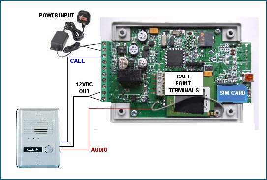
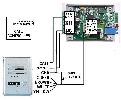
Step 2: Connect power, call button and audio cable to call point terminals.
Step 3: Program the system by SMS text messages as follows
a) Firstly, enable the Inputs to be used as GSM intercom Call Buttons (WMOD)
You must enable the Inputs as Call Buttons to use the intercom feature. Wire call button into Input 1 or 2 then...
To enable Input 1 as a call button Input, send Text: ;+WMOD=1;
To enable Input 2 as a call button Input, send Text: ;+WMOD=2;
To enable both Input 1 & 2 as a call button Inputs, send Text: ;+WMOD=12;
b) Set Up the Numbers called by Call Button 1 (PDEA)
To retrieve the current settings, send Text: ;PDEA;
- You will receive a reply as follows:
;ATN1=;ATN2=;ATN3=;ATN4=;ATN5=;RTNA=15;
Select 'Forward Message' from your mobile phone text options & choose the intercom's SIM No.
Edit the message as required by adding the the numbers you want the intercom to call in order starting at ATN1 as follows:
;+ATN1=077965124589;ATN2=02074561254;ATN3=;ATN4=;ATN5=;RTNA=15;
c) Set Up the delay timer before dialing the next number (RTNA)
The time delay is set at 15 seconds by default. If you want to change this time up or down, send text: ;+RTNA=xx; where 'xx' = the time in seconds.
d) Set Up the Numbers called by Call Button 2 (PDEB)
To retrieve the current settings, send Text: ;PDEB;
- You will receive a reply as follows:
;BTN1=;BTN2=;BN3=;BTN4=;BTN5=;RTNB=15;
Select 'Forward Message' for your mobile phone text options.
Edit the message as required by adding the numbers you want the intercom to call in order as follows:
;+BTN1=077965124589;BTN2=02074561254;BTN3=;BTN4=;BTN5=;RTNB=20;
e) Set Up the delay timer before dialing the next number (RTNB)
The time delay is set at 15 seconds by default.
If you need to change this up or down, send text: ;+RTNA=xx; where 'xx' = the time in seconds.
f) Door Release
The User hangs up the call & speed dials the G2 back from an authorised phone. When the G2 is called back, an audible beep is played from the call point speaker as the door unlocks. The entry event is logged.
i) The number of the SIM card in G2 should be set as a preset 1 press speed-dial on the User's phone
ii) The preset speed-dial button can be used for door release at any time
MISCELLANEOUS PARAMETERS (SIM, Device & GSM Intercom)
The device has various parameters that can be customised to suit the User or application. Not all are relevant to every application so they are grouped into categories.
a) General Settings (defaults shown)
MUT=0 (Silent or Ringing Sound during intercom call connection)
- Send SMS text: ;+MUT=1; to mute the ringing sound
- Send SMS text: ;+MUT=0; to enable the ringing sound
MIC=0 (Call Point Microphone Level 0 - 15)
- Send SMS text: ;+MIC=x; where x = 1 - 15 to increase the MIC level
SPK=80 (Call Point Speaker Level 75 - 100 max.)
- Send SMS text: ;+SPK=xxx; where x = 75 - 100 to increase the SPK level
LOT=60 (Line Open Time - to limit the length of intercom calls 0 - ~ seconds)
- Send SMS text: ;+LOT=90; to increase the line open time
- Send SMS text: ;+LOT=45; to decrease the line open time
ADF=90 (Automatic Dial - Calls Administrator 1 at interval to prevent prepay SIM card expiry 0 - ~ days)
- Send SMS text: ;+ADF=180; to increase the days before automatic calling
- Send SMS text: ;+ADF=75; to decrease the days before automatic calling
MRT=1 (Mute Tone - Disables beep when outputs are activated)
- Send SMS text: ;+MRT=0; to disable the output activated beep
- Send SMS text: ;+MRT=1; to enable the output activated beep
b) SIM Card / Mobile Network Settings (defaults shown)
SPO=1 (If using an 02 UK PAYT SIM card this parameter must = 10 - Do not change if not using 02 UK prepaid)
- If using an 02 PAYT SIM card, send this text message first before any other: ;+SPO=10;
CC1= (SIM Credit Checking - The following examples are for UK 02 & Vodafone PAYT networks only)
- To set up 02 UK PAYT SIM card, send SMS text: ;CREF.=1;CC1=*#10#;
- To set up 02 IRELAND PAYT SIM card, send SMS text: ;CREF.=1;CC1=*#100#;
- To set up Vodafone PAYT SIM card, send SMS text: ;CREF#=2;CC1=*#1345#;
Contact Support regarding this feature on other networks. Not all networks support credit checking SMS code.
LCV=4 (Low Credit - If the CC1 & CREF above are set correctly, alerts will be sent when credit reaches £x)
- Send SMS text: ;+LCV=3; to set the level of whole pounds your credit must reach before alerts are sent
- Alerts will be sent at intervals of 1 in your currency until a minimum of 1 is reached. Alerts stop at 1 to prevent last credit being used.
TST=24 (Set in Hours, a test message is sent at this interval to check the SMS Text Alerts are operational)
- Send SMS text: ;+TST=168; to set the test alert for every 7 days
ALC=1 (Auto Log Clear - When G2 reaches 1015 events, it automatically clears the Log)
- Send SMS text: ;+ALC=0; Manual Log Clear (an SMS text alert will be sent to TN1 at 900 & again at 1015 events)
- Send SMS text: ;+ALC=1; to enable Automatic Log Clear
When Authorised Administrator (TN1) receives the 'event log full' alert, make a back up of the required log data either by SMS text or PC and then manually erase the entire Event Log memory by sending SMS text: ;LCLR;
LNG=0 (Language - 0 = English)
- Send SMS text: ;+LNG=x; where 'x' = number 0 - 7 for various languages.
English=0
Italian=1
Slovenian=2
Croatian=3
Dutch=4
French=5 (not supported)
Spanish=6 (not supported)
German=7
SDCLR (Erase all parameters from SIM card. Returns all parameters back to default)
- Send SMS text: ;+SDCLR;
IMPORTANT: WAIT AT LEAST 5 MINUTES AFTER SENDING THIS COMMAND. DO NOT SWITCH OFF OR CONNECT / DISCONNECT ANYTHING
The RED LED will flash while the erasing is in progress. The G2 will automatically reset at the end and when the BLUE LED flashes again the device is ready for re-programming.
c) Device Reset (defaults shown)
MRES (Manual Reset - to manually reboot the GSM module only - will not erase settings)
- Send SMS text: ;MRES; to manually reboot the GSM module and re-register the SIM card on the network
SSRES (Manual Reset - to manually reboot the GSM module & processor - will not erase settings)
- Send SMS text: ;SSRES; to manually reboot the GSM module & micro-processor. This completely restarts the device as it would if it was powered down and back on; without actually having to switch the power off.
ARST=168 (Automatic Interval Reset in hours to automatically reboot GSM module - will not erase settings)
- Send SMS text: ;+ARST=90; to reboot the GSM module and re-register the SIM card on the network
SMS TEXT PRINT COMMANDS (automatically prompt G2 for current settings)
G2 has a unique SMS text prompt system whereby you can request all or certain parameters before making any changes. You may need to adjust a User or setting quickly. This is the best way to do it.
After receiving the information, select 'forward message', make your changes to the information & send it back to G2. The unit will be instantly updated. It's a good idea to include the '+' in the command sent ie: ;+CLP1=......; or alternatively you can send the same 'PRINT' command again to retrieve the data to see if you changes were applied.
a) Receive all Current Parameters Set (PALL)
- Send this SMS text: ;PALL;
Note: If you send ;PALL; by SMS, you will receive at least 30 text messages with the settings. This command is best used by PC & normally by the Installer for the purpose of fault finding within the parameters set.
b) Receive all Current Caller ID Control Settings, Authorised Callers & Vacant Slots (PCLP)
- Send this SMS text: ;PCLP;
c) Receive all Authorised Administrator Mobile Numbers and/or Vacant Number Slots (PTN)
- Send this SMS text: ;PTN;
d) Receive the Security Level ie: Which Administrators are allowed to program G2 (PSL)
- Send this SMS text: ;PSL;
e) Receive which alerts are 'Linked' to which Authorised Administrators (PLN)
- Send this SMS text: ;PLN;
f) Receive Input configuration ie: How long they must be active before alerts are sent (PID)
- Send this SMS text: ;PID;
g) Receive Output configuration ie: How outputs are set to switch; pulse, latch, timed (POS)
- Send this SMS text: ;POS;
h) Receive Current Output States ie: Are they active or not (PORC)
- Send this SMS text: ;PORC;
i) Receive Direct Output configuration ie: How outputs switch on Input / Event activity (POD)
- Send this SMS text: ;POD;
j) Receive programmed labels for the device Name / Location & Inputs (P#)
- Send this SMS text: ;P#;
k) Receive the Current Settings of the Miscellaneous Parameters (PPA)
PPA will return a list of general parameters; UDC (self clock update), HTN (not relevant), SCV (Prepaid SIM card validity period), TST (Test SMS), MNF (not relevant), MIC (microphone level), SPK (speaker level), LCV (low credit SMS limit), LNG (not relevant), LOT (line open time), LOGN (event log limit by SMS), ADF (automatic dial function), ARST (automatic reset), OP1 (inverse output 1 relay contact), OP2 (inverse output 2 relay contact), BUZ (buzzer), SPO (SIM parameter offset -
- Send this SMS text: ;PPA;
l) Receive the remaining SIM card credit (PCC1)
- Send this SMS text: ;PCC1;
- This feature will only work if the paremeters ;CC1; & ;CREF; are set according to the SIM card being used. 02 & VF UK are shown below:
- To set up 02 UK PAYG SIM card, send SMS text: ;+CREF.=1;CC1=*#10#;
- To set up 02 IRELAND PAYG SIM card, send SMS text: ;+CREF.=1;CC1=*#100#;
- To set up Vodafone PAYG SIM card, send SMS text: ;+CREF#=1;CC1=*#1345#;
No other UK Networks are supported. Contact Support for more info.
m) Receive the Current Settings for the GSM Intercom Feature - BUTTON 1 (PDEA)
- Send this SMS text: ;PDEA;
n) Receive the Current Settings for the GSM Intercom Feature - BUTTON 2 (PDEB)
- Send this SMS text: ;PDEB;
LED DISPLAY
The LED's are to indicate what is happening on the device at any given time.
1. BLUE GSM Network Signal Strength (1 Flash = Low Signal / 5 Flashes = Maximum Signal)
If the Blue is on solid, the device is not connected to the network. You will find that red is also on or flashing on/off. This indicates something is not right with the network and could be antenna, or SIm card related.
2. RED Device / Connection / Network Fault
Red will flash during start up to indicate the processor is reading the SIM card. It will also flash if the device is erasing data when prompted. It should not be on at all during normal operation. If the Red is solid or flashing at any time other than the initial 30 - 60 seconds after power up while the device logs onto the network; you have a fault somewhere.
Red indicates something is not right in general and could be to do with the network, antenna, SIM card, connections or hardware damage. Check carefully starting with your wiring connections. Then try the device in a different 'open air' location. Failing that try a differnt network SIM card. Visually inspect the hardware and look for any obvious damage or foreign objects on the PCB.
3. YELLOW GSM Network (1 Flash/sec. = Registering & 1 Flash per 5 sec. = On Network)
The Yellow is only related to the Network initial registration & then reporting that the device is currently on the network. If the Yellow is not flashing once every 5 seconds, it is not on the GSM Network.
TROUBLESHOOTING
Check the status of the LED's first and check the LED descriptions to provide a general idea of what to look at first.
a) Device won’t connect to the GSM network
- Move the G2 to another location
- Try another SIM card or check the SIM card PIN code request is disabled
- Connect the optional external antenna
- Check supply voltage is sufficient
b) General audio interference during intercom calls
- Make sure you have all cable screens (metal bare wire around coloured cores) connected to GND
- The bare wire screen of the 2 pair audio cable must be connected to GND both ends
- Use a Switch mode 12VDC regulated power supply 1 amp minimum.
- Don’t run other equipment on the same power supply as the GSM intercom
- Keep the intercom audio cable & antenna away from mains power cables as best as possible
- Keep the antenna outside any metal enclosures or fit an optional external antenna
- Connect any metal panel enclosures to GND especially if mounted to a steel post
- Check the audio terminal connections are not loose (yellow, white, brown, green)
- Lower the microphone level on the GSM call panel
c) Whistling or interference all the time or during a call
- Lower the microphone level on the GSM call panel
d) Device won’t respond and blue LED is solid
- GSM Network Signal issue
- SIM card not inserted correctly
- Try different SIM card
- Check antenna connection
- Make sure antenna is not inside a metal enclosure
e) SMS Programming won't work
- Check SL (Security Level). The number you are sending the commands from may not be authorised
- Check SIM card is on the network (see LED display)
f) Voicemail cuts in before my intercom call transfers to the second number
- Change RTNA (button1 ) or RTNB (Button 2) to a higher number. This will make the call ring longer.
g) Speaker Level is too low / high
- Adjust SPK up or in Miscellaneous Parameters
h) Red LED is solid
- Check connections and polarity on GSM controller & intercom interface PCB
- Check PCB components visually to locate obvious damage
- Check power supply input voltage is sufficient
i) Red LED is Flashing
- Fit external antenna
- Relocate controller
- Change Network SIM card
j) If your issue is not listed here
- Contact your Supplier for Support
[1]N/O: Normally Open [Open going Closed] This is a commonly used switching configuration for most devices. The contact is open when in a deactivated state. When it activates, the contact closes.
N/C: Normally Closed [Closed going open] This switching method is most commonly used with magnetic locks. Magnetic locks require power to be applied during a deactivated state. When activated, the contact opens and removes power from the magnetic lock thus releasing it.