Industrial IT and Embedded Systems
Group 4

DIT:168
Industrial IT and Embedded Systems
Final Report
Group 4
Team members:
Emanuel Mellblom
John Sundling
Tigistu Desta
Isar Arason
Ioannis Gkikas
Sami Sindi
Awele Azimoh Supervising TA: DarJa Linkova
2 Project Organization & Planning 4
3 Conceptual Ideas of Algorithmic Aspects 7
3.2.1 Lane Following Flowchart 11
4 Necessary algorithmic fundamentals 16
4.3 Communication Protocols 20
5.4 Lane Following - Stop Line Detector 24
6.3 System Sequence Diagrams 31
7. Hardware and Software Integration 34
7.2 Hardware Connections Block Diagram 35
7.3 Communications Component Diagram 36
8. Hardware, Software, and Integration Tests 37
10.1 Technical Problems: Hardware 40
10.1 Technical Problems: Software 40
10.4 What Could Have Gone Better 41
1 Introduction
Ever Since cars were mainstreamed, manufacturers and engineers were actively trying to find ways to make driving safer, cleaner, more cost efficient and affordable. That need to innovate has never been greater than it is today.
53 million vehicles entered the global market from 2000-2013. Since 2013 car sales have increased expositionally reaching upwards of 80 million a year. From 2014-2017 it is estimated that more that 300 million cars were sold globally [4].
The Industry predicts that by 2020 self-driving cars will be a common sight in countries like UK, USA, and Finland. Auto manufacturers and IT giants such as Google,Uber, Tesla and Volvo, to name a few, are all switching focus to autonomous driving, and the demand for skilled software engineers with background on the matter is at an all time high [1].
In DIT168 the goal was to develop an autonomous 1:10 scale car capable of performing three main scenarios. Those scenarios were parking, overtaking and lane following.
In the parking scenario the goal was to give the car the ability to perform a parallel parking maneuver and park at the side of the road. In Overtaking the goal was to get the car to overtake an obstacle that was placed in the driving lane of the car. The goal of the lane following scenario was to give the car the ability to follow a lane while driving and stop if the car detects a stopline.
To our help in realizing this goals we used an open source software called OpenDaVINCI which had functionalities such as inter process communication and much more. We also used OpenCV for image recognition.
The majority of this project is written in the programming language C++.
The system was compiled and built into a Docker image that was later runned in order to use the system.
OpenDaVINCI also holds a simulator that was used to test the algorithmic ideas that we had to see if they would work in reality.
We also had access to a room with a test track where we could test our implementation in a realistic environment.
The hardware we had at hand for completing this project was a 1:10 scaled rc car with a motor, esc, steering servo, sensors, Arduino mega and a web camera.
In this report we will discuss the software architecture of our implementation as well as describing the algorithmic fundamentals and algorithmic ideas realized in this project.
2 Project Organization & Planning
The group followed a roadmap consisting of phases and milestones. This roadmap was designed around the demos and presentation time frames set by the course coordinators. The group also implemented a process that divides the group into 3 smaller teams with each team responsible for deploying a specific feature. The teams are:
- Lane Following Emanuel and John.
- Overtaking Tigistu and Awele.
- Parking Ioannis, Isar, and Sami.
The process focused on practices such as; pair programming, daily meetings, and open and constant communication.
Phases | Milestones |
Concept and Planning |
|
Environment Setup |
|
Feature Development |
|
Tuning and Optimization |
|
System Deployment |
|
The following Gantt chart depicts the time periods of each activity over the development life-cycle of the project.

The following table shows what parts of the project each group member worked on, as well as each group member’s github handle.
The link to our repository is the following:
https://github.com/emanuelmellblom/opendlv.scaledcars
Name | Github handle | Contribution |
Emanuel Mellblom | emanuelmellblom | - Lane Following, Link - Overtaking Link - Setting up raspberry PI for running our images - Hardware - Reports |
Awele Azimoh | xINGRAMx | - Overtaking, Link - Image processing(Hough line transformation),Link - Hardware - Reports |
John Sundling | garzoc | - Arduino, Link - Proxy, Link - Lane Following, Link - Hardware - Reports |
Isar Arason | i-arason | - Parking, Link - Arduino, Link - Reports |
Tigistu Desta | Hawassa | - Overtaking, Link - Reports |
Sami Sindi | samisindi | - Parking, Link - Image processing - Reports |
Ioannis Gkikas | funkyfisch | - Parking (theory and implementation) , Link - Hardware & Arduino, Link - Reports |
All members contributed equally in the writing of this report. | ||
3 Conceptual Ideas of Algorithmic Aspects
3.1 Parking
Initially the members involved in parking started with developing an algorithm in a more theoretical level, based on the vehicle’s parameters, geometry and trigonometry. On a normal car, reverse parallel parking is done in 3 steps (A towards B, B towards C and C towards D), as shown in figure 3.1.1 . However this method does not apply for the provided vehicle and requirements, as the steering angle is not steep enough for a deep enough displacement on the x axis within the maximum displacement on the y axis ( parking space ), which can be proved both mathematically for given parameters, and in practice, by trial and error.
We then thought of adding steps to the total trajectory that the vehicle has to follow while parking. The extra steps added displace the vehicle deeper into the parking space by going forwards and backwards a specific number of times, with specific steering angles, so the vehicle can be placed parallel to its initial position.
Further examining the 3.1.1 figure, we can derive that the arcs AB and CD are 45 degree arcs and correspond to displacements on y axis and x axis. Using the odometer we can instruct the vehicle to move for a certain time that corresponds to each arc. Using this we can derive the arcs that need to be driven forwards before arriving at the desired total dx while at the same time staying within the maximum parking space limit. We further refined the whole process with adding a preliminary step that moves the car even more forward so that it can start driving the first curve (AB) without sacrificing the parking space while at the same time not touching the front parking obstacle.
Unfortunately due to time constraints, hardware problems involving the inconsistent odometer readout and the difficulty to use the vehicle’s ackermann angle (wheels would not always turn exactly at the desired maximum), the above could not be implemented fully for demonstration purposes. Instead a more practical approach was used in the end, a rough approximation of the above algorithm along with tweaking of some parameters. Using the above algorithm we could reproduce a successful parking maneuver that worked for the majority of tests and we could even minimize the parking space to up to 52 centimeters in length. However this approach is prone to failure due to many reasons, even battery levels and a slight change in traction of the wheels.
Figure 3.1.1

The parking algorithm consists of two states: Search and Park. Search uses both IR sensors on the right side for object detection. The car derives the space size by adding up distance traveled while no objects are visible on the right side. The proxy provides the current speed of the car, so the car derives the distance traveled each tick by multiplying its current speed by the time passed since the last tick.

In the Search state, the car will slowly move forward, counting the distance traveled.
If an obstacle is detected, it will clear the distance counter. When the distance counter reaches the minimum space requirement, the car will move on to the Park state. The Park state is a sequence of time-triggered states affecting speed and wheel angle. This will move the car approximately one car length back and one car width to the right. Upon completion of the parking sequence, it moves back until it detects an object. The states are configurable by using the configuration file, thus enabling another vehicle, with different requirement specifications to apply the same implementation but with different parameters.
Below is a high level sequence diagram showing the overview of a message sequence between parking components.
This will be explained in greater detail under section 6 (p.33)
3.2 Lane Following
The lane follower reads an image from the camera proxy which is processed with the help of some algorithms that are included in the opencv library like blur, grayscale and Canny. We then apply our algorithm that scans the image for white pixels and then calculates a steering angle, compresses it and sends it to the proxy which sends it to the Arduino.

A more detailed description of this algorithm is found below (p.11).
3.2.1 Lane Following Flowchart
The following flowchart is based on the pseudocode on page 12, which depicts part of the lane detection related to our custom voting algorithm; that filters out “bad” scan lines (noises), and average the result of the “good” ones.
This algorithm is used together with Canny edge detection and a slightly altered version of the PID controller provided in the example code for laneFollower.

loop loop scan pixel right side loop end when white pixel is found or reached end of image loop scan pixel left side loop end when white pixel is found or reached end of image if has scanned until a specified stop line if in over 50% of the times scanning the right side returned a result loop create group by comparing every scanned line on the right side to the previous scanned line if not connected create new group else push to the current group loop end take the average scanned distance of the biggest group else if in over 50% of the times scanning the left side returned a result loop create group by comparing every scanned line on the left side to the previous scanned line if not connected create new group else push to the current group loop end take the average scanned distance of the biggest group else if there is at least one line scanned on the right side use the line furthest away else if there is at least one line scanned on the left side use the line furthest away else go straight forward end if loop end when loop has scanned until a specified stop line |
3.3 Overtaking
The following diagram show the different states of the vehicle when starting the Overtaking component.
The car drives following the lane powered by laneFollower logic. When the front ultrasonic sensor detects an object of distance = 50cm, it will trigger Overtaker component. This causes it to start avoiding the object by turning left. When the car detects the inner lines, it will start laneFollower again, but this time for the inner lane. The car will continue driving on the inner lane side until the right front IR sensor stops detecting any objects. The car will then turn right again until it detects the outer lane line, after which the car will go back to its original state and resume laneFollower on the right lane.

The following sequence diagram demonstrates the sequence of events and the operations executed within the overtaking state as structured in the system.

Firstly, once the front ultrasonic sensor reads a value that fits the specified condition for object-detected, it leaves the lane following state, prints “object detected”, and changes to the state “turn to left lane”. When it reaches a specified angle on the left lane a counter starts counting from zero. If the front right infrared sensors reads a value greater than zero and less than or equal to twenty, the counter stops and it moves on to third state, “drive on left lane”, in which lane following takes over. The car continues driving on the left lane as long as both front right and rear right infrared sensors read values. Once the front right sensor reads zero, it moves to the next state, “turn to right lane” which is the left lane turn in reverse. The car steers at specified angle to the right lane until the counter reaches zero and matches the distance measured by the odometer. Once these conditions are met, it returns to the initial state and repeats the steps stated above if an obstacle is detected.
loop lane follow on the right lane if front ultrasonic sensor is less 45, greater than zero , not turning to the left lane, not driving on the left lane and not turning to right lane loop object is detected, it turns to left laner at a specified angle else if it is turning to the left lane, loop counter starts counting from zero, odometer measures distance while steering the left lane else if the front right infrared sensor reads a value greater than zero drive on leftlane else if car is driving on the left lane while both front right IR and rear right IR sensors are greater than zero, loop continue lane following state on the left lane if front right infrared sensor is equal to zero break turn to the right lane elseif turntorightlane counter decreases until it reaches zero, drives until it matches measured odometer distance else if continue lane following on the right lane
|
4 Necessary algorithmic fundamentals
Image 4.1 shows the sensor layout of the car. The yellow triangle is representing the viewing angle of the camera attached to the car which is 90 degrees according to the datasheet of the camera.
The two red triangles represents the Ultrasonic sensors in the front of the car which have a max measuring distance of around 6 meters and a minimum measuring distance of 3 cm. The angle of the sensor beam is around 45 degrees.
The three blue triangles represents the IR sensors of the car and they have a max measuring distance of 30 cm and a min measuring distance of 3 cm.


4.1 Sensors
The way we deal with noise from the IR sensors is by taking several measurements and averaging them for a more accurate result. However, this method is not perfect, so we limited the range to 20 cm. Readings past this distance become excessively noisy.
The ultrasonic sensors are reasonably accurate for values below 50 cm. Because of their consistent accuracy, we chose not to average multiple readings, but instead decided to set a maximum measurement distance. A benefit of this approach is that the Arduino takes less time to process each iteration of the main program loop. To improve this even further, we decided not to use the angled ultrasonic sensor as it was not necessary. This allowed us to read from the single ultrasonic sensor twice since we didn’t have to switch between them every tick.
We also raised all of the sensors, both IR and ultrasonic, because the ultrasonic was detecting the black tape on the test track, and raising the IR sensors reduced noise.
In the above image we show how the sensors were tilted up to improve the correctness in their readings.


4.2 Camera

There was little we could do with the camera to improve the lane following. We disabled the autofocus on the camera because it lost focus due to the shaking which greatly affected its performance.
In the image to the right, the loss of focus from the camera can be seen resulting in the edge detector having trouble detecting any edges in the image.


The image to the right is the image taken after turning off the auto focus on the camera leading to a consistent edge detection.


This is a side by side image comparison between Canny and Hough line transform image. Hough line transform is implemented to improve the image processing. It eliminates small spaces between lines detected on the track which improves the image calculation implemented in lane follower. The addition of this creates a restriction in which calculations are only done on the lane the car is focused on. This mitigates the problem of drawing the scanline outside the track as seen above in the Canny image. the only fault is that at intersections and sharp curves, it tends to connect the end of dashed line on the track to the left lane, which causes it to steer to the wrong lane.
4.3 Communication Protocols

The Arduino and the proxy communicate by sending a single byte to each other. The proxy will always send a vehicle-control byte, while the Arduino sends a sensor-data byte to the proxy.

Both Packets and how their data is processed can be seen in the image to the right.
The sensor-data byte contains an ID that indicates which sensor the value comes from. The IDs are as follows:
Sensor | ID |
Back right IR | 1 |
Front center ultrasonic | 2 |
Front right ultrasonic | 3 |
Rear IR | 4 |
Front right IR | 5 |
Odometer | 6 |
- Notice that there is no sensor with ID zero, this is so that when the buffer is set to NULL it might conflict with the sensors readings, resulting in sensor ID zero to return an inaccurate reading of 0.
Why this protocol?
We previously tried using a separate protocol which parses a string into a float value and a character, which specified the function of the float value. For example, if the character is ‘A‘ that means that the value represents a steering angle.
This method of transferring data turned out to be too slow and unreliable since it is not guaranteed that the entire message will arrive at once. This is the main reasoning to use our byte protocol, but we had to trade accuracy for performance due to the compression rate.
5 Implementation Details
5.1 Arduino
The way messages are sent between the Arduino and application layers is by packing the message into one byte. In this byte the first three bits acts as either an ID for which sensor the value is from, or represents the car’s speed. The last five bits are used to represent the value from a sensor, or the steering angle for the wheels. More information on the protocol can be found in Section 4.
5.2 Proxy
The proxy is a simple intermediate layer. It does little more than acting as a middleman in the communication between the Arduino and the application layer. All values received from the Arduino are stored in a shared memory buffer which only contains the latest sensor values. Old values will automatically be erased by the proxy.
5.3 Overtaking
This is the implementation of our overtaking algorithm. The algorithm is described in more detail under section 3.
Step 1. Declaring needed variables. |
//Sensor ID int INFRARED_FRONT_RIGHT = 5; int INFRARED_REAR_RIGHT = 1; int ULTRASONIC_FRONT_CENTER = 2; //2 //States bool turnToLeftLane = false; bool turnToRightLane = false; bool goForward = true; bool driveOnLeftLane = false; bool readOdometerFirstTime = false; //Distance int drivedDistance = 0; int drivedDistanceDevided = 0; |
Step 2. If object is detected within the specified range, start turning to the left and switch state. |
if(readSensorData(ULTRASONIC_FRONT_CENTER) < 45 && readSensorData(ULTRASONIC_FRONT_CENTER) > 0 && !turnToLeftLane && !driveOnLeftLane && !turnToRightLane){ //5.5 sendSteeringAngle((-60*M_PI)/180, m_speed); //-60 turnToLeftLane = true; goForward = false; } |
Step 3. Turn out to left lane, turn left until the right front IR detects the obstacle. At the same time measure the traveled distance with the odometer. When the front IR detects the obstacle switch state. |
else if(turnToLeftLane){ if(!readOdometerFirstTime){ resetOdometer(); readOdometerFirstTime = true; } drivedDistance += readOdometer(); int irValue = readSensorData(5); if(irValue > 0 && irValue < 18){ driveOnLeftLane = true; turnToLeftLane = false; readOdometerFirstTime = false; drivedDistanceDevided = (drivedDistance/3); } } |
Step 4. Drive on left lane. Here lane following is used to drive on the left lane as long as either the front right IR or the back right IR sees the object. When the front ir sensor no longer see the object switch state. |
if(driveOnLeftLane){ while((readSensorData(INFRARED_FRONT_RIGHT) > 0 || readSensorData(INFRARED_REAR_RIGHT) > 0) && getModuleStateAndWaitForRemainingTimeInTimeslice() == odcore::data::dmcp::ModuleStateMessage::RUNNING){ c=getKeyValueDataStore().get(odcore::data::image::SharedImage::ID()); if (c.getDataType() == odcore::data::image::SharedImage::ID()) { has_next_frame = readSharedImage(c); } if (true == has_next_frame){ processImage(); } sendSteeringAngle(steering, m_speed);
if(readSensorData(INFRARED_FRONT_RIGHT)==0){ break; } } driveOnLeftLane = false; turnToRightLane = true; } |
Step 5. Turn back to right lane, make a turn to the right lane again after passing the object. The odometer is used to make sure the turn is performed in the right distance. After the traveled distance is completed switch state. |
else if(turnToRightLane){ if((readSensorData(INFRARED_REAR_RIGHT) > 0 || readSensorData(INFRARED_FRONT_RIGHT) == 0) && turnToRightLane > 0){ if(!readOdometerFirstTime){ resetOdometer(); readOdometerFirstTime = true; } drivedDistanceDevided -= readOdometer(); sendSteeringAngle((45*M_PI)/180, m_speed); odcore::base::Thread::usleepFor(100000);
if(drivedDistanceDevided <= 0){ turnToRightLane = false; goForward = true; readOdometerFirstTime = false; drivedDistance = 0; } }else{ sendSteeringAngle((35*M_PI)/180, m_speed); odcore::base::Thread::usleepFor(90000); } |
Step 6. Go forward again by using lane following. Continue with lane following until a new object is detected. |
else if(goForward){ if(m_stopline){ odcore::base::Thread::usleepFor(150000); sendSteeringAngle(steering, 3); odcore::base::Thread::usleepFor(2000000); m_stopline = false; } sendSteeringAngle(steering, m_speed); } } |
5.4 Lane Following - Stop Line Detector
Step 1. Declare necessary variables. |
CvPoint leftStopPoint, rightStopPoint; CvScalar leftPixel, rightPixel; int leftOffset = (temp->width/2)-50; int rightOffset = (temp->width/2)+50; leftStopPoint.x = leftOffset; leftStopPoint.y = 0; rightStopPoint.x = rightOffset; rightStopPoint.y = 0; |
Step 2. Search for white pixels at the left and right offsets. |
//Find potential stopline pixels at left offset for (int i = temp->height-12; i > CONTROL_SCANLINE-40; i--){ leftPixel = cvGet2D(temp, i, leftOffset); if(leftPixel.val[0] >= 200){ leftStopPoint.y = i; break; } }
//Find potential stopline pixel at right offset for (int i = temp->height-12; i > CONTROL_SCANLINE-40; i--){ rightPixel = cvGet2D(temp, i, rightOffset); if(rightPixel.val[0] >= 200){ rightStopPoint.y = i; break; } } |
Step 3. Check if the detected pixels are within a specified range to see if it is a somewhat horizontal stopline. If that is the case then set m_stopline to true which will lead to the car setting its speed to a standstill for two seconds and then starts to move again. |
int range = 20; if((leftStopPoint.y - rightStopPoint.y > -range) && (leftStopPoint.y - rightStopPoint.y < range) && ((leftStopPoint.y+rightStopPoint.y)/2 < temp->height) && ((leftStopPoint.y+rightStopPoint.y)/2 > 325)){ if(this->m_newStopLine) m_stopline = true; else m_stopline = false; this->m_newStopLine=false; }else{ m_stopline = false; this->m_newStopLine=true; } |
5.5 Parking
Step 1. Declare necessary variables and load parking sequence from the config file. |
double parkTimer = 0; bool parked = false; KeyValueConfiguration kv = getKeyValueConfiguration(); const int stage0 = kv.getValue<int32_t>("parking.stage0"); const int stage1 = kv.getValue<int32_t>("parking.stage1"); const int stage2 = kv.getValue<int32_t>("parking.stage2"); const int stage3 = kv.getValue<int32_t>("parking.stage3"); const int stage4 = kv.getValue<int32_t>("parking.stage4"); const int stage5 = kv.getValue<int32_t>("parking.stage5"); const int stage6 = kv.getValue<int32_t>("parking.stage6"); const int stage7 = kv.getValue<int32_t>("parking.stage7"); const int stage8 =kv.getValue<int32_t>("parking.stage8"); const int stage9 =kv.getValue<int32_t>("parking.stage9"); const int minimumTimeToFindSpace = kv.getValue<int32_t>("parking.minimumTimeToFindSpace"); const int32_t INFRARED_FRONT_RIGHT = 5; const int32_t INFRARED_REAR_RIGHT = 1; const int32_t INFRARED_BACK = 4; |
Step 2. Move forward and count the current space size. If an object is blocking the space, reset the counter. |
TimeStamp currentTime; double deltaTime = (currentTime.toMicroseconds() - lastTime.toMicroseconds())/1000; lastTime = currentTime; if (currentSpaceSize <= minimumTimeToFindSpace) { // Go forward. sendMotionData(0, 5); // Get odometer value - probably approx in cm //currentSpaceSize += readSensorData(ODOMETER); currentSpaceSize += deltaTime; // Check if an object is blocking the space. // If it is, reset space size int rear = readSensorData(INFRARED_REAR_RIGHT); int front = readSensorData(INFRARED_FRONT_RIGHT); if((rear < 20 && rear != 0) && (front < 20 && front != 0)){ currentSpaceSize = 0; } } |
Step 3. Once a space has been found, execute the predefined movement sequence. |
else if (currentSpaceSize > minimumTimeToFindSpace && parked == false) { parkTimer += deltaTime; if (parkTimer < stage0) { sendMotionData(0,3); } else if (parkTimer < stage0+stage1) { sendMotionData(0, 5); } else if (parkTimer < stage0+stage1+stage2) { sendMotionData(60, 1); } else if (parkTimer < stage0+stage1+stage2+stage3) { sendMotionData(0, 2); } else if (parkTimer < stage0+stage1+stage2+stage3+stage4) { sendMotionData(-60, 1); } else if (parkTimer < stage0+stage1+stage2+stage3+stage4+stage5) { sendMotionData(60, 5); } else if (parkTimer < stage0+stage1+stage2+stage3+stage4+stage5+stage6){ sendMotionData(-60, 2); } else if (parkTimer < stage0+stage1+stage2+stage3+stage4+stage5+stage6+stage7 ) { sendMotionData(60, 5); } else if (parkTimer < stage0+stage1+stage2+stage3+stage4+stage5+stage6+stage7+stage8 ) { sendMotionData(-60, 2); } else if(parkTimer > stage0+stage1+stage2+stage3+stage4+stage5+stage6+stage7+stage8+stage9 && parked == false) { int back = readSensorData(INFRARED_BACK); if (back > 10 || back == 0) { sendMotionData(0, 2); } else { sendMotionData(0,3); parked = true; } } |
6. Software Architecture
6.1 Component Diagram
The purpose of this section is to describe the high level architecture of the system.

We decided to use a layered architecture for our main system structure. By using this architecture, we were able to group components with related functionalities into discrete layers. Each layer in our architecture is dependent on the layers below it. The component diagram above shows how the architecture is divided into four different layers. In the Low level layer we have components that directly communicate with hardware, such as actuators and sensors.
Above the low level layer, there is the middleware layer. The components in this layer are the proxy and a specialized camera proxy. The purpose of these components is to communicate with the low level layer components as well as storing data in the data structures shown in the shared memory layer above it.
The application layer contains the high level application components. These are lane following, overtaking, and parking. These components hold the logic for their respective tasks. They use bidirectional communication with the data structures in the shared memory layer below it to interact with the car hardware.
6.2 Class Diagram
The class diagram, found on the next page of this report, is a more detailed illustration of the system’s components. The main components are grouped into packages with their respective internal functionalities described in form of classes.
The communication pathways and their directions in the system are indicated by the arrows connecting the different classes and packages.
The Lane Following package holds the functionalities related to the lane following component, those functionalities are reading a shared image, image processing, lane detection, detect stop lines, calculate steering angle as well as send data.
The sendData component is responsible for storing the calculated steering angle as well as the desired speed in the shared Memory called sensory memory.
The Overtaking package is allowed to use and interact with the lane following, meaning that when no obstacle is detected on the road the car keeps on going with the lane following. The classes/functionalities within the overtaking package are Detect obstacle, read odometer Data, read sensor data, perform overtaking, as well as a sendData class responsible for storing steering data and desired vehicle speed in the shared memory called sensorData.
Next is the package called Parking which holds the classes necessary for performing the parking functionalities. Theses classes are read sensor data, read odometer data, detect parking space, performe parking as well as a component for storing the desired steering angle and speed in the sensor memory data structure.
On the right side of the diagram we can see the components related to communication mainly the two proxies, a package called Arduino can also be seen which is the lowest level component in this system architecture.
The first component on the right side of the diagram is the Camera Proxy which have the functionalities of communicating with the camera on the car, mainly taking pictures. Once an image is captured the CameraProxy stores the image in a data structure called CreateSharedImage.
Under the CameraProxy we have a package called Proxy which is mainly responsible for communicating with the Arduino package and stores data in the described data structures.
The classes/functionalities in the package Proxy are; CreateSharedMemory, store data in sharedMemory, serialConnection and readData from Serial.

The Arduino package contains the lowest level functionalities/classes in the system that is responsible for directly communicating with the hardware on the car, as well as sending data over a serial connection to the Proxy. The classes in the Arduino package are serialConnection, which is responsible for connecting to a serial port, getData, which receives data on a serial connection, and sendData, which is responsible for sending data over a serial connection.
There are also classes for reading ultrasonic sensors, reading IR sensors, reading odometer. Then there are classes responsible of controlling the actuators of the car such as setSteeringAngle, setSpeed and controlLEDlights.
6.3 System Sequence Diagrams

The sequence diagram above describes the order of operation in which the classes of the lane following component performs their respective task, as well as the input and output of each specific class/functionality.
The sequence starts with the car camera continuously capturing images and storing them in a data a structure called sharedmage.
The next steps of the sequence runs in a loop where the first event is read sharedImage which reads out an image from the shared image memory. Next, the image goes through image processing where the image is processed according to the description explained in section 3 of this report. The output of this stage is a processed image that the next component in the sequence uses, called the lane detection. This step is described in more detail in section three of this report, the output of the lane detection stage is a distance measurement that is used by the next stage in the sequence called calculate steering angle. In this stage a steering angle
is calculated by using a PID controller.
The output of this stage is a steering angle which becomes the input to the proxy that returns the steering angle as well as the desired speed to the car where the low level components takes care of adjusting the speed and steering of the car.

In the sequence diagram above, the stages made up by the classes in the overtaking component can be seen.
The sequence starts with the components of the low level layer continuously reading the sensors of the car. Those sensor readings is then sent to the proxy class which outputs a data into a segment of shared memory called sensor memory.
This shared memory is then accessed by the object detector which in a loop continually looks to see if an object is within a specified range described in more detail in section three. If a detected object exists the lane following class takes over the sequence and performs the overtaking functionality by outputting a steering angle to the send data class which in turn sends this data to the shared memory where it is accessed by the proxy and sent to the car via serial communication where the low level layer changes the speed and steering angle accordingly.

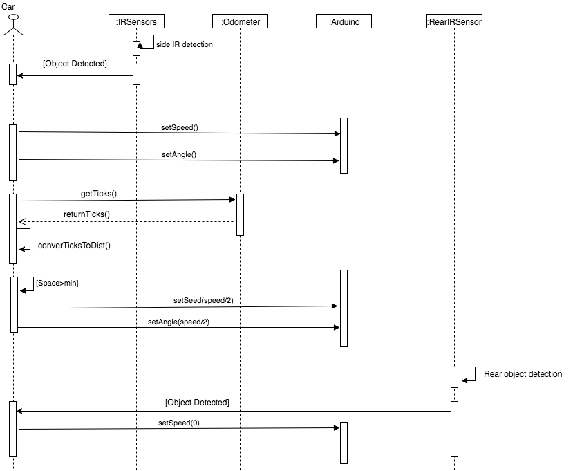
The sequence diagram above depicts the parking procedure. The car will first set the car of the speed via the shared memory. Once this is done, it will start searching for a space to park in. While no objects are detected on its right side, it will count up the empty space until it hits the minimum required space size. If at any time before this limit is reached an object is detected, the counter will be reset and it will start counting the next free space.
Once a suitable space is found, the parking sequence is initiated. This is a series of preprogrammed movement and turning commands executed in sequence to move the car into the detected space.
7. Hardware and Software Integration
7.1 Deployment View

The diagram above describes how our software components are deployed on different types of hardware and use different kinds of execution environments. It also describes the different types of communication between the different devices in the system.
The leftmost device in the diagram is the computer running the software components of the Application layer, as well as the Middleware layer described in section 6 in this report. The hardware this runs on may be a single board computer or any computer running a Linux operation system with Docker installed. In our system, the hardware was a raspberry PI model 2 or a laptop, respectively.
The execution environment that runs on this device is Docker where the individual Docker images are runned.
The device in the middle of the diagram is the microcontroller used to directly control the hardware of the car. In our case, the microcontroller was an Arduino Mega 2560. This device runs software components described in the class diagram in section 6.2 of this report. This device communicates with the computer running the Docker image via a USB serial connection. It uses digital and analog signals, as well as the I2C protocol to communicate with the hardware components of the car.
The device on the right in the diagram is the car which holds the hardware components of the system, such as actuators and sensors. It communicates with the Arduino device in order to transmit the sensor readings and get steering angles and speed of the car.
7.2 Hardware Connections Block Diagram
This diagram describes hardware connections of the system in form of a block diagram. The central point of connection in the system is the Arduino Mega 2560. Around this all peripherals that is connected to the system can be seen. This includes the sensors, rc receiver, voltage regulator, esc, and the LED lights of the car. The lines between the Arduino and the peripherals are the wires that connect them, drawn in their respective colors.

The text associated with the wires describes which pin each wire is
connected to. For example, the signal wire of the rear IR sensor is connected to pin A5 on the Arduino.
7.3 Communications Component Diagram
This component diagram shows the communication process between the lower level components of the system and the two proxies. The lowest layer holds hardware components and the layer above it holds the different communication types in the form of components. The Low level layer holds the components that runs on the Arduino described in section 7.1. And communicates with the middleware layer that holds the proxies and the hardware layer. The camera in the hardware layer communicates directly via USB with the camera proxy that in turn stores images in the sharedImage.

8. Hardware, Software, and Integration Tests
8.1 Hardware Tests
Our hardware testing was mostly focused on measuring the accuracy of the sensors on the real car.
As an example, we used a measuring tape to get the accuracy of the odometer, ensuring the sensor returned about the same distance as the actual traveled path of the car.
We also tested the infrared and ultrasonic sensors in the same way by placing an object at a predetermined distance and checking if the sensor returns the same distance as the actual measured distance.
We had some problems with the car not reversing properly. We used a separate Arduino Nano to isolate the motors from the rest of the car, then tested various aspects of the motor using a new Arduino sketch, but did not find the problem. We later found out the motors were set to the incorrect settings, which we then fixed using the ESC calibration card.
8.2 Software Tests
Our software testing revolved around mostly testing the implementation of algorithms and looking at the output and manually comparing it to an expected output.
As an example when were were implementing our filter for the lane follower we positioned the car on the track then added several prints to the code. After that we noted what the expected output from these prints should be if the algorithm was worked correctly. Finally we ran a manual tested a looked at the output.
8.3 Integration Tests
Integration tests were performed in a manual manner. An example of this procedure is the integration between the Overtaker and the proxy. When the two components were integrated, we conducted manual tests where we watched the input/output of the Arduino, the proxy, and the overtaker component to see that the values were consistent between the different components of the system.
9. References
9.1 Lane Following
- Computer vision:
- OpenCv Canny.
- http://docs.opencv.org/2.4/doc/tutorials/imgproc/imgtrans/canny_detector/canny_detector.html
- http://docs.opencv.org/3.0-beta/doc/py_tutorials/py_imgproc/py_houghlines/py_houghlines.html
- OpenCV blur
- Matrixes
- PID controller
- OpenDaVINCI documentation
- Lane-detection
- https://medium.com/@galen.ballew/opencv-lanedetection-419361364fc0
- https://medium.com/computer-car/my-lane-detection-project-for-the-self-driving-car-nanodegree-by-udacity-36a230553bd3
9.2 Overtaking
- OpenDaVINCI documentation
9.3 Parking
- Ackermann steering details
9.4 Proxy
- OpenDaVINCI documentation
9.5 Arduino/Hardware
- Ultrasonic sensor datasheet (SRF08)
- Rc controller datasheet
- ESC datasheet
- Ir sensors datasheet
- LED lights datasheet
- http://www.seeedstudio.com/document/pdf/WS2812B%20Datasheet.pdf
- https://github.com/adafruit/Adafruit_NeoPixel
- Arduino libraries
9.6 Additional Resources
- [1]The New York Times, Article - Accessed on 23-May-2017 [https://www.ft.com/content/3922742a-0d56-11e7-a88c-50ba212dce4d]
- [2]Lecture slides
- [3]Christian Berger. (2014). From a Competition for Self-Driving Miniature Cars to a Standardized Experimental Platform: Concept, Models, Architecture, and Evaluation. Journal of Software Engineering for Robotics, May 2014, 63-79 ISSN: 2035-3928.
- [4] Statista, Articel - Accessed 23- May-2017 [https://www.statista.com/statistics/200002/international-car-sales-since-1990/]
10. Project Retrospective
10.1 Technical Problems: Hardware
- We ran into multiple hardware issues starting with replacing the car due to having a broken differential. This occurred a day before the car safety check.
- We seemed to always have a problem with the different connection ports and wirings on the car - the jumper cables were replaced multiple times.
- We had a problem with controlling the ESC when we wanted to use reverse. This turned out to be caused by a setting on the ESC which we changed by using the programming card.
- We had problems with sensors detecting obstacles that should not be detected, such as the tape on the floor on the test track in the testing room. This was fixed by tilting the sensors up. This is better described in section 3 of this report.
- After a bit of testing on the real car, we found out that the autofocus of the webcam was causing problems. We solved this by turning the camera's autofocus off on system startup. This is described in more detail in section 3 in this report.
- As previously mentioned, it has been quite difficult using the odometer properly, especially depending upon it for validation of car position and using it for precise trajectory calculations. We experimented with different libraries to try and derive the most optimal software solution to this impediment.
10.1 Technical Problems: Software
- Some of the group members ran OpenDaVINCI on Ubuntu 16.04 Virtual machines in the initial phase of the project. It later turned out that it did not work properly with using the real hardware. The solution was to set up a dual boot environment on the machines., unfortunately this wasn’t possible for some Mac machines due to MacOs security limitations, these were later patched by 3rd party software on a later date.
- We had a problem with sharedImages being invalid when distributed from the camera proxy. We fixed this by removing the line --user=odv in the Docker run command.
- We found the documentation for OpenDaVINCI could have been more comprehensive.
10.2 What Went Well
- Highly productive cooperative environment between the team members.
- Open and continuous communication.
- The decision to split our group into three smaller teams working on each of the tasks in parallel instead of completing the tasks in sequence turned out to be a good decision.
- We decided to use Github as a version control and code sharing system which worked out well.
- Being flexible and adaptive to changes
- Collaboration on documents that concerns the project by using google Docs and store this in a group shared google Drive.
- Slack and facebook were used for communicating between the group members as well as deciding when we should have meetings and so on.
10.3 What We learned
- More knowledge on C++
- We learned the fundamental concepts of self driving vehicles.
- Learned Image recognition with openCV
- We gained more knowledge in hardware and hardware control by using an
Arduino as microcontroller. - Working with PWM signals
- Applying higher level of math and physics on cyber-physical systems
- Importance of Docker as a development and deployment tool for seamless continuous integration
- Experience in a working environment of an industrial setting, involving cyber-physical systems
10.4 What Could Have Gone Better
- If we had more time to work on the project we would have been able to improve our implementations of the components of our system.
- Less time could have been spent on setup of Docker and ODV
- Some direct access to extra components could save a lot of time in order to overcome hardware problems