supergen performance shower pumps INSTALLATION GUIDE SUPERGEN BRASS POSITIVE & UNIVERSAL BRASS
This is a high performance, high specification pump range with precise installation requirements. Please pass all manuals on to the householder after installation. It is necessary to retain proof of purchase in order to facilitate any warranty claim. technical helpline : 01793 820142 QUALIFIED INSTALLER TO CARRY OUT INSTALLATION All rights reserved. Updated February 2023 |

|
Your Supergen Shower Pump has been designed and manufactured in England. If correctly installed and not misused, it will give many years of reliable service. Installation and operation must comply with local regulations and accepted codes of good practice. The use of this product requires experience and knowledge of the product.To ensure satisfactory operation, we ask that you read the instructions before commencing installation. Then carry out, in sequence, each step as described. The instructions MUST be followed, otherwise the pump may be damaged and your warranty invalidated. Note: Please dispose of any packaging supplied in an environmentally friendly and legal manner. |
|
When unpacking and installing pump, ensure that no foreign particles (such as solder or dust, etc) are allowed to enter the outlets; these will cause the flow switch to malfunction and damage the pump impeller. Do not allow any solder flux to come into contact with any part of these pumps. |
|
|

|
Use 22 mm pipes to and from the pump.
|
|
DO NOT USE ANY JOINTING COMPOUNDS
|
|
DO NOT CONNECT DIRECTLY TO THE WATER MAINS SUPPLY DO NOT USE ANY JOINTING COMPOUNDS OR TAPE |
|
|
|
Do not position outlets in the cold water storage tank directly below the inlet from the water mains supply in order to prevent air from being drawn into the pump or hot water cylinder. |
|
DO NOT USE ANY JOINTING COMPOUNDS OR TAPE. DO NOT ALLOW SOLDER FLUX TO COME INTO CONTACT WITH THE PUMP. ENSURE UNRESTRICTED FLOW IN THE FLEXIBLE HOSES. | ||
| ||
| ||
| ||
| ||
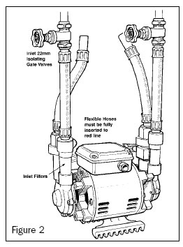
Do not connect metal (brass / iron) fittings directly onto pump inlets / outlets. Use of these hoses will ensure strain and vibration-free watertight connections. Care should be taken with pump positioning so that the flexible hoses are not kinked. Max bend allowance of 45 degrees. | ||
33 mm. Failure to fully insert connections will cause leaks. | ||
| ||
| ||
NOTE: If you are fitting a UNIVERSAL shower pump (Supergen N60TX, N80TX, N121TX, N150TX, N21SX, N37SX), please refer to section 13 UNIVERSAL HEAD PUMPS - for additional connection details. | ||
|
Maximum hot water temperature at the pump must not exceed 60°C (140°F) in accordance with BS6700:2006, to eliminate the risk of limescale and cavitation. |
|
Either Surrey, York, Warix or Essex flanges can be used for the hot water cylinder, depending on the cylinder type and installation.We do not recommend that you take the hot-water supply directly from the top of the hot water cylinder, as entrapped air may cause problems such as airlocks in the supply pipe. |
|
The low voltage pump installation kits are supplied with 3 metres of connecting lead. The connecting leads between the pump and the isolating transformer can be extended up to about 15 metres. Use min. 1.0 mm2 cable. |
DANGER - ELECTRIC SHOCK - DEATH OR SERIOUS PERSONAL INJURY ENSURE COMPLIANCE WITH IEE REGULATIONS Before starting any work on the product, make sure that the power supply has been switched off and that it cannot be accidentally switched on. |
|
|
|
|
|
|
|
|
Observe colour coding as follows:
Ensure the earth lead is at least as long as the other two leads.
Follow procedure for startup before switching on the power supply. Comply with IEE regulations. Fit the terminal box cover before you switch on the power supply. The pump switch should be left in ‘on’ position at all times for normal operation of the system. |
12. PUMP START UP |
DO NOT START THE PUMP UNTIL IT HAS BEEN FILLED WITH LIQUID. BEFORE STARTUP, FLUSH THE SYSTEM WITH CLEAN WATER AND DRAIN TO REMOVE POSSIBLE IMPURITIES. |
|
|
|
|
|
|
|
|
|
|
|
|
The first few times the pump is used, the insulating varnish used on the pump motor may give off an odour. This is perfectly normal and will diminish with use. |
Shaft seal run in - The seal faces are lubricated by the pumped liquid, meaning that there may be a certain amount of leakage from the shaft seal. When the pump is started for the first time, or when a new shaft seal is installed, a certain run-in period is required before the leakage is reduced to an acceptable level. The time required for this depends on the operating conditions. Under normal conditions the leaking liquid will evaporate. As a result, no leakage will be detected. |
Run the pump for five minutes or more at least once every 4 weeks in order to prevent the pump from seizing up. Scale buildup can cause the pump parts to stick. |
|
Automatic universal head shower pumps are designed to operate automatically in installations when the shower outlets are above the level of the cold water storage tank. The shower pump types Supergen N60TX, N80TX, N121TX, N150TX, N21SX and N37SX feature independent pressure and flow controls, with built-in non-return valves and stainless steel expansion tanks in each pump end. This system ensures complete hot and cold water system isolation with stable control over a very wide flow range. | |
| |
Dry running protection - avoids damage to seals caused by water starvation. This condition is possible if the water supply fails, for instance if the water storage is insufficient or the pump strainers are blocked. If the pump runs for 60 seconds with an insufficient water supply, the pump will stop and ‘lock out’. | |
Resetting the “lock out” - to reset the pump, switch off the power supply for ten seconds. When the power supply is switched on again, the pump will run for a few seconds to recharge the tanks. If it continues to run and there is no demand, this would indicate that one of the following situations is still present:
Continued dry running will lead to overheating of the shaft seals and eventually to a water leak. | |
Connecting the pump - follow the general instructions in this book, but please note the following.
| |
Operating instructions - Taps and valves used on the ‘pressure system’ must be fully turned off when not in use to avoid that the pump runs reciprocating on and off. | |
Installation options - lavatory cisterns If the pump is to supply a lavatory cistern, take the precautions below to avoid frequent starting and stopping of the pump due to low flow rates. If possible, best practice is to supply the cistern from the mains water supply. If this is not possible, we recommend a ‘Torbeck’ or equilibrium valve. If either of these are not possible, the following instructions should be followed:
Washer dryers Only brass pumps must be used for these applications. |
|
|
|
|
|
|
In certain applications, for example steam cabinets, it may be necessary to increase the pressure. Consult the appliance manufacturer. |
|
Before starting any work on the product, make sure that the power supply has been switched off and that it cannot be accidentally switched on. |
One of the most common causes of pump problems is air in the system. |
Fault | Possible Cause | Remedy |
|
| Switch on the power supply. |
| Replace the blown fuses. If the new ones blow too, check the electrical installation. | |
| The thermal protection resets automatically within one to two hours. | |
| The pump must be installed with vertical outlet ports (flow switches). | |
| Increase the water flow to at least 0.5 lpm. | |
2. The pump runs but delivers no water. |
| Open the isolating valves. |
| Close the isolating valves, clean the strainers and re-open the valves. | |
3. The flow from the shower drops. |
| Close the isolating valves, clean the strainers and re-open the valves. |
4. The pump runs continuously. |
| Ensure that there are no leaks and that all taps and appliances are closed. |
| Purge any air in the system. With the pump not running, allow maximum flow by removing the shower handset and allowing the hose to hang into the shower tray or bath. Operate maximum hot and cold flow for at least five minutes each. For fixed head showers remove the shower rose and connect a length of hose, hanging into the shower tray or bath. | |
| Make sure that the flow switch can operate correctly and there is no debris in the flow switch. | |
| Adjust or replace as appropriate. | |
5. The pump pulses. |
| Ensure that taps or other outlets are not causing water hammer. A low pressure non-return valve can be fitted on the outlet pipe of the pump. Contact your installer. |
6. Unstable water temperature or noisy pump. |
| Fit a Surrey flange and study the pipe layout. There should be no high points where air can collect. |
| Reduce hot water temperature. The maximum hot water temperature at the pump is 60’C. | |
| Remove debris. | |
7. Noisy pump. |
| Place the pump on a concrete slab to reduce noise. |
8. Hose connection leaking. |
| Make sure that the hose washers and strainer washers are fitted. Check that the plastic nuts on the hoses are tight. |
16. ADDITIONAL FAULT FINDING FOR UNIVERSAL MODELS |
|
| Contact the helpline for adjustment or replacement details. |
2. The pump pulses. |
| Contact your installer. |
| Check the system for leaks. | |
| Check the non-return valves and replace if necessary. | |
3. The pump does not run even though there is demand. |
| Open a tap to increase the flow demand. |
| Adjust or replace as appropriate. | |
| Switch off the power supply for 10 seconds to reset. See Dry Running Protection in section 13. | |
4. Pump hunts when shutting down. |
| Adjust the tank air pressure setting. |
| Replace the printed-circuit board (PCB) | |
5. Pump hunts when starting up. |
| Open a tap to increase the flow demand. |
| Adjust or replace as appropriate. |
17. TECHNICAL DATA |
Operating Conditions | ||
Relative Humidity | Maximum 95% | |
Storage Temperature | Minimum -20°C, Maximum 70°C | |
Ambient Temperature | Maximum 40°C | |
Liquid Temperature | See pump nameplate | |
Minimum Starting Flow Rate | 0.5 lpm | |
Start / Stop Frequency | Maximum 100 per hour | |
Electrical Data | ||
Rated Current | See pump nameplate | |
Insulation Class | 155 (F) | |
Miscellaneous Data | ||
Enclosure Class | IPX2 | |
Supergen Positive 60TX, 80TX, 121TX, 150TX, 21SX, 37SX | Supergen Universal N60TX, N80TX, N121TX, N150TX, N21SX, N37SX | |
Maximum System Pressure | 6.0 Bar | 6.0 Bar |
Inlet Head | 1 - 20 m | 1 - 8 m |
Maximum Developed Pump Head | 13 - 41 m | 21 - 41 m |
Supply Voltage | 1x 230V, 50 Hz | 1x 230V, 50 Hz |
Rating | Continuous Operation | Continuous Operation |
18. DISPOSAL |
This product or parts of it must be disposed of in an environmentally sound way:
The crossed-out wheelie bin symbol on a product means that it must be disposed of separately from household waste. When a product marked with this symbol reaches its end of life, take it to a collection point designated by the local waste disposal authorities. The separate collection and recycling of such products will help protect the environment and human health. |
19. INSTALLER CHECKLIST |
Your Supergen shower pump will only work properly if it has been installed correctly. The installer should complete the following checklist ensuring it is signed and dated. While you are installing this shower pump, tick the following important instructions to confirm installation guide has been followed. If you need assistance, please contact the Supergen Service helpline on 01793 820142.
When the installation is completed please sign and date and pass on to the customer.
| ||
At least 1 metre head from water level in cold water storage tank to top of pump | ||
| ||
| ||
| ||
| ||
| ||
| ||
| ||
| ||
| ||
|
Print Name | Signature | ||||
Company Name | Date |
To register your Supergen shower pump, please complete and return this form via post, email or online.
Pump World, Unit 11 Woodside Road, Swindon, SN3 4WA. enquiries@pumpworld.co.uk, www.pumpworld.co.uk
CONTACT DETAILS |
Your Full Name | |||||
Address & Post Code | |||||
Telephone Number | |||||
Email Address | |||||
PUMP DETAILS |
Supergen Model Name Located on the pump nameplate. | |||||
Pump Serial Number Must be included. Located on the pump nameplate, typical format: W00000 - 000 - 0000 | |||||
Supplied By Please include contact, company name and branch location (if applicable). | |||||
Installed By Please include installer name, company name and contact phone number. | |||||
Date of Purchase | Date of Installation |
INSTALLATION DETAILS This part should be completed with the help of your installer. All questions must be completed. |
Type of Cylinder Fitting (Essex Flange / Warix Flange / Surrey Flange / York Flange / 1st Vent Take Off) If other, please specify. | Pipe Sizes Suction / Discharge | ||||||
Do you have a Cylinder Thermostat? | Is Suction Dedicated? ie. no draw offs prior to the pump. | ||||||
If yes, confirm Thermostat Setting The hot water temperature at the pump must not exceed 60’C. |
| Are Flexible Hoses straight? Flexibles must be kept straight. | |||||
If no, do you have a Temperature Regulator? If not, your warranty is invalid. | Is the pump located on the floor, by the cylinder? | ||||||
If applicable, confirm Temperature Regulator Setting |
| If no, please advise pump location |