
Draft Jul. 09
15.2 Modulation Amount range. 17
15.3 CV Control Amount range. 18
19.1 Updating The patch (via browser) 19
1 Intro
According to Greek mythology, the Oneiroi are dark-winged creatures that emerge from their cave each night to deliver dreams and nightmares. With this module, we’ve created a more practical way for you to receive their messages, even when awake.
2 What is Oneiroi?
Oneiroi is a self-contained experimental synth focused on ambient pads and drone-like soundscapes.
It features a full stereo signal path, 3 oscillators (2 mutually exclusive), 4 effects, and a looper. It also includes self-modulation and a randomizer.
Oneiroi is based on Rebel Technology’s OWL platform.
3 Features
- Powered by the latest OWL revision (mk3), with 24-bit 48 kHz stereo audio (32-bit internal processing)
- Stereo input with three gain levels and a two-colored LED peak meter.
- Stereo output
- 5-second looper with continuous speed control (from 2x in reverse direction to 2x in forward direction)
- Sine oscillator
- Stereo Supersaw oscillator with detune control, inspired by the JP-8000
- 2048-sample dynamic wavetable oscillator (aliased) that uses the looper buffer, with offset control
- Single v/oct input for the three oscillators and unison control
- Filtering unit with four different types: low-pass, band-pass, high-pass, and comb filter. The filter can be freely positioned along the effects chain
- 3-band resonator with tune and feedback controls
- A 2-tap echo with controls over time and density
- Reverb with macro control for size, filtering, and direction
- Eight short-throw faders for controlling volumes (exponential) and effects amount (constant power), with relative CV inputs
- CV controls for all the primary parameters, four of them can be dynamically assigned to the secondary ones as well
- Possibility to record either the stereo input or the module’s output
- Various types of self-modulation with configurable routing and control over level and speed
- External synchronization via sync input (supported clock speed from 30 BPM to 300 BPM)
- Powerful randomizer with four different targets, three levels of intensity and undo/redo
- Soft take-over functionality for re-coupling parameters’ positions and values after randomization, with LEDs showing where the value is in relation to the position of the control.
4 Front Panel controls
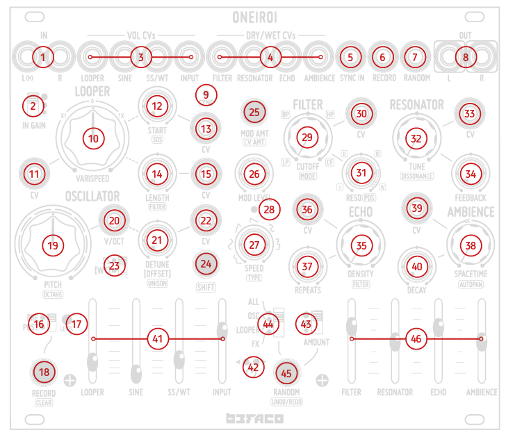
- Stereo input. The left channel normals to the right channel.
- Input gain switch.
- Volume CVs. It is affecting the levels of the four signal sources. Range 0 to 10V.
- Dry/wet CVs. It is affecting the four effect units. Range 0 to 10V.
- Sync in. Synchronizes the LFO and Delay time to an external source, and reset the looper to the start point. Accept triggers of a minimum of 1V.
- Record IN. Gate Input for recording. Start recording at a high level (>1V) and stop recording at a low level (0V).
- Random IN. Randomize the parameters when high (>1V).
- Stereo output. Eurorack level. The left channel normals to the right channel.
- Sync LED. Will light up when a positive voltage is received at the sync trigger input [5]
- Looper playback Speed.
- Looper playback speed CV. Range -5V to 10V.
- Looper start position.
- Looper start position CV. Range -5V to 10V.
- Looper loop length.
- Looper loop length CV. Range -5V to 10V.
- Pre/post recording selector.
- Audio level Peak Meter. Shows on green the signal level either Input or internal system signal depending on the Pre-Post Recording selector (16). It lights up red when the signal is clipping.
- Record button.
- Pitch control. For the sine oscillator and the supersaw/wavetable
- V/Oct input. Range -5V to 10V.
- Detune/offset. Controls either the supersaw detuning or the wavetable offset depending on the position of the Oscillator Mode Switch [20]
- Detune/offset CV. Range -5V to 10V.
- Oscillator Mode Switch. Supersaw (up position) or wavetable (down position) selector
- Shift button. For accessing secondary functions, marked on the front panel with inverted graphics like for example AUTOPAN
- Modulation/CV Amount button. Access a secondary function of the knobs controlling the amount of internal Modulation and external CVs levels.
- Modulation Level. Master control for the intensity of the modulation.
- Modulation frequency.
- Modulation LED. Modulation voltage, visual indicator.
- Filter cutoff.
- Filter cutoff CV. Range -5V to 10V.
- Filter resonance.
- Resonator tune.
- Resonator tune CV. Range -5V to 10V.
- Resonator feedback.
- Echo density. Delay time control for the echo effect.
- Echo density CV. Range -5V to 10V.
- Echo repeats. Feedback control for the echo effect.
- Ambience spacetime. Macro control for size, filtering, and direction of the reverb.
- Ambience spacetime CV. Range -5V to 10V.
- Ambience decay.
- Volume faders. Manual controls for the four audio sources. When their equivalent CV input jacks are used (see number 3), they become attenuators of the incoming CV.
- Catch-up LEDs. While in “Catch Up” knob behavior (see Chapter 5),
they indicate in which direction the potentiometers must be turned to match them with the real value of that parameter.
They also indicate key points of some parameters like pitch and Looper speed.
- Randomization amount.
- Randomization target.
- Randomize button.
- Dry/Wet faders. Manual controls for the Dry/Wet of the four FX processors. When their equivalent CV input jacks are used (see number 4), they become attenuators of the incoming CV.
5 Structure
The two main blocks of Oneiroi are the sources and the effects.
The sources are the following:
- Sine oscillator
- Supersaw oscillator/wavetable oscillator (mutually exclusive)
- Looper
- External input (recorded when in PRE mode)
- Resample output (only for recording in POST mode)
The sine oscillator and the supersaw-wavetable combo share the same pitch control
but have two separate volume controls.
External input and resample output are mutually exclusive when recording, but the
external input has volume control and can be sent directly to the effects.
The effects units are:
- Filter
- Resonator
- Echo
- Ambience
The effects are connected in series. Each fader controls the dry/wet ratio of a specific effect in the signal path. When a fader is at its lowest position, the signal passes on to the next unit unaffected.
The filter is the only unit that can be moved to any position along the effects chain.
6 Shift button
This button is used to access secondary parameters (identified on the panel by labels with a white background).
There are two different ways of using the shift button:
- Momentary: Hold the Shift button at the same time as the chosen parameter is changed. It will deactivate at button release.
- Toggle: A single press of the button, without holding, toggles the Shift function on and off
If the SHIFT button light is ON, the labels with a white background will prevail.
Parameters with only one label will ignore this button.
All changes made on the SHIFT page must be saved to persist after a power cycle. (See Chapter 4.3)
7 Mod/CV amount button
This button is used for two things:
- To access the modulation mapping. (see section “Modulation” below) The button will blink RED to indicate the modulation mapping page.
- To access the CV mapping of the 9 primary CVs. ( see section “CVs” below). The button will Blink Green to indicate the CV mapping page.
Additionally, this button is used for saving the current state of the module. (see next chapter)
8 Manual Saving
When using Oneiroi, there are instances where the position of the manual controls does not match the actual parameter value. In these cases, it is important to perform the SAVE operation to ensure that all parameters maintain their state after power cycling.
To perform SAVE, Hold the MOD AMT Button for two seconds. The Buton's LED will blink to indicate that the saving operation has been performed.
Buffer content is not saved by the SAVE operation, so it is not retained between power cycles.
9 Synchronization
The SYNC IN input allows for synchronizing Oneiroi with an external source. The
module needs a couple of seconds to align to the external sync and at the same time
to go back to internal sync when the external is removed.
When no external source is connected, the module uses an internal clock frequency
of ~0.2 Hz derived from the looper’s buffer. The SYNC LED lights up accordingly.
Regardless of whether it’s internal or external, the synchronization is used for:
- Retriggering the looper
- Clocking the internal modulation
- Synchronizing the echo time and the ambience’s auto-pan
It is advisable to use a clock with a trigger per bar or less, such as a trigger every four bars
or so, as the same clock is used for these three different tasks, including resetting the
looper.
10 Sound Sources
10.1 Input
The input allows external sound sources to be processed through the Oneiroy.
The module has a stereo input whose signal goes simultaneously to the looper and
The effects chain.
If only one cable is connected to the stereo input's “L(M)” connector, the signal will be split to both L and R channels, allowing them to be processed by the stereo signal path.
The input gain can be changed with the switch:
- the top position offers the greatest gain. It allows the
connection of high-impedance sources like contact microphones,
- the middle position is perfect for line-level sources
- The bottom position is suited for connecting the output of
other Eurorack modules.
The INPUT fader controls the input level that goes directly to the effects chain.
10.2 Looper
This unit can be used for recording and playing back approximately five seconds of either
the audio coming from the stereo input (PRE) or the audio sent to the module’s output
(POST), depending on the position of the PRE/POST switch.
The bi-color LED monitors the signal level coming from the stereo input when the
PRE/POST switch is set to PRE or the level of the signal sent to the output when set to POST.
The LED turns red when the signal is clipping.
The VARISPEED knob controls both the direction and the playback speed, from 2x in the
reverse direction at 0% to 2x in the forward direction at 100%. The playback can never be
stopped unless the VARISPEED knob is at 12:00 where the looper is stalled. There are virtual
detents at -1x, 0 and 1x.
The LENGTH knob changes the size of the loop, with an exponential curve, from ~8 ms at 0%
up to the full length at 100%. The START knob allows you to pick the starting point of the
loop.
At the minimum loop length, the unit acts as an oscillator whose note is C3 at +/-1x, C2 at
+/-0.5x, and C4 at +/-2x speed.
When a trigger is received at SYNC IN, the looper restarts at the point specified by START.
Recording is activated/deactivated using either the RECORD button or the RECORD input.
The button’s LED lights up accordingly.
The RECORD button can be operated in two ways:
- Toggle. A single press of the button, without holding, toggles the recording on and off
- Momentary. Holding the button pressed allows for recording until the button is released (holding the button while the looper is recording pauses the operation until released).
The RECORD input acts as a gate and turns the recording on for the duration of the high signal. While the looper is recording, the RECORD button will blink when using either the SHIFT or MOD/CV button.
The buffer is prefilled with white noise by default, so the looper channel can be useful
without the need to record anything.
The buffer content can be cleared by holding the SHIFT button and pressing the RECORD
button.
SOS (Sound On Sound, meaning how much of the previously recorded material is kept
while recording) can be set by holding the SHIFT button and turning the START knob:
at 0% the old material is constantly replaced, and in between it fades away
progressively slower and at 100% it never fades away. During recording, the SOS
is processed through a DJ-style filter whose response can be changed by holding the
SHIFT button and turning the LENGTH knob: at noon no filter is applied, going clockwise
an HPF is applied, going counter-clockwise an LPF is applied.
10.3 Oscillators
The module provides three stereo oscillators: one simple sine, one supersaw (inspired by
the Roland JP-8000), and a wavetable. While the sine oscillator can be used alone, the
other two are mutually exclusive and can be selected with the relative switch. Depending
on which one is selected, the DETUNE knob controls either the detuning of the 7 saws of
the supersaw or the selection of one of the 32 wavetables dynamically extracted from
the looper buffer.
The full pitch range of the oscillators is 8 octaves, from C0 to C7. The PITCH control
is centered on C and spans 6 semitones on either side. The current octave can be
selected by holding the SHIFT button and turning the PITCH knob.
The v/oct input is common for the three oscillators, is summed to the PITCH knob,
and tracks 10 octaves on the 0-volt to 10-volt range. The frequency is clipped if outside
the supported range.
Holding the SHIFT button and turning the DETUNE knob allows for altering the unison for
the oscillators: the frequency of one of the two sine’s channels and that of both
the supersaw and the wavetable oscillators are lowered one octave down at 0% and
raised one octave at 100% (default is 50%, unison).
11 Effect units
11.1 Filter
This unit is either a 2-pole multimode filter that can be switched between
low-pass, band-pass, and high-pass filtering, or a comb filter. The type can be selected
by holding the SHIFT button and turning the CUTOFF knob. When the unit is used as
a multimode filter, the CUTOFF knob controls the filter frequency cutoff (approximately
from 10Hz to 22kHz), while when used as a comb filter the knob controls the position of
the notches.
The peculiarity of this unit is the presence of a chaotic noise generator that is
activated when the RESONANCE knob goes past 75% and whose output is summed
and filtered with the input. The noise is audible even when no input is provided.
The filter can be placed at one of the four possible positions in the effects chain by
holding the SHIFT button and turning the RESO knob:
- At the beginning of the chain
- Between the resonator and the echo
- Between the echo and the ambience unit
- At the end of the chain
11.2 Resonator
This unit is based on three different instances of a stereo comb filter tuned on
related frequency bands. By turning the TUNE knob, the base frequency of the
instances changes using three different ratios. The FEEDBACK knob creates a
sustained resonance that, at 100%, makes the unit self-oscillate. By holding the
SHIFT button and turning the TUNE knob, the resonance can be made more
dissonant (default is 0%).
11.3 Echo
This unit is based on a 2-tap stereo ping-pong delay whose time ranges from 10 ms to
4 seconds using the DENSITY knob. The REPEATS knob allows you to repeat the
delayed sound from one time at 0% to infinite at 100%.
When a clock is received at the SYNC IN, the DENSITY knob becomes a divider.
By holding the SHIFT button and turning the DENSITY knob it is possible to process the
echo through a DJ-style filter: at noon no filter is applied, going clockwise an HPF is
applied, going counter-clockwise an LPF is applied.
11.4 Ambience
This unit is very loosely based on a Schroeder reverberator and its peculiarity is the
macro control for size, filtering, and direction using the SPACETIME knob, with the
smallest size and brightest tone at 50% and the biggest size and darkest tone at either 0%
or 100%. With values < 50% the input signal is reversed. The DECAY knob controls
how long the tail will take to fade out.
This unit is provided with an auto-panner synchronized with either the external sync input
or with the frequency of one looper cycle. By holding the SHIFT button and changing
the SPACETIME knob, it is possible to change the amount and the
frequency’s division/multiplication at the same time: At 0% no auto-pan, at 100%
full auto-pan at 8x the base frequency, in between there are 16 different ratios
(default is 50%).
12 Modulation
This unit provides the module with self-modulation.
The modulation type can be selected by holding the SHIFT button and turning the
SPEED knob (the types morph smoothly from one to the other).
There are 7 types of modulation that you can choose from:
- Chaos
- Sine LFO
- Ramp LFO
- Sawtooth LFO
- Square LFO
- Sample & Hold
- Envelope Follower
The amount of modulation can be changed with the MOD LEVEL knob. This control is a “modulation master” that prevails over all modulation mappings.
The Envelope Follower is placed just before the looper so that it can follow either the module’s input or output depending on the position of the PRE/POST switch.
The SPEED knob allows to slow the base frequency of the modulation down to 1/16 times
or to speed it up to 16 times with common time divisions and multiplications.
When unsynced, the base frequency is calculated on the looper buffer length and is ~0.2Hz,
so in this case the SPEED ranges from ~0.01Hz to ~3Hz.
The same applies when the module is synced, but the base frequency in this case
is that of the received clock. The maximum frequency is capped at 80Hz.
For the modulation based on the envelope follower, the SPEED knob controls the slope of
the envelope curve, from slow at 0% to fast at 100%.
By default, the modulation is sent to the filter’s CUTOFF. Still,
every knob (excluding those of the modulation itself) has an associated control that
allows to specify the amount of modulation received by the relative parameter. The
controls are accessed by entering the modulation mapping mode (MOD AMT button)
and moving the knob of the parameter that you want to be affected by the modulation,
from 0% to 100%.
This modulation mapping can be erased while in modulation mapping mode by pressing both the RECORD
and RANDOM buttons at the same time.
Be advised that all changes made must be manually saved to persist after a power cycle. (See Chapter 4.3)
13 Randomizer
The Randomizer acts in different ways depending on the position of the two switches.
The TARGET switch permits the selection of which units are affected by the randomization:
- All units (looper, oscillators, and effects)
- Oscillators only
- Looper only
- Effects only
The AMOUNT switch allows you to specify the amount of variation applied to the current value of the target parameters:
- The top position is for full-range randomization
- The middle applies a potential variation of +/- 20%
- The lower position applies a potential variation of +/- 2% respectively.
The oscillators’ pitch is randomized by semitones. The faders and the supersaw/wavetable selector are excluded from the randomization, as are all the secondary parameters accessed with the SHIFT button, the modulation mapping, and the CV mapping.
To randomize, select both the target and the amount and press the RANDOM button or
send a trigger at the RANDOM input.
The randomization can be undone and redone by holding the SHIFT button and pressing
the RANDOM button. At any time, the parameters can be reset to the actual position of
their controls by holding the SHIFT button and pressing both the RECORD and
RANDOM buttons simultaneously.
All changes the Random command makes must be manually saved to persist after a power cycle. (See Chapter 4.3)
14 Voltage Control
Each Oneiroi knob (except the modulation knobs) has a dedicated control to set the amount of CV it receives. To access the controls, enter the CV mapping mode by pressing the SHIFT and the CV AMT buttons together. Then, adjust the knob you want to be affected by the CV from 0% to 100% (the default is 100% for all primary parameters).
In addition, the 4 CVs of the effects, which are initially assigned to the main parameters, can also be similarly assigned to secondary parameters.
CV routing can be reset back to default (100% for all primary parameters) by simultaneously pressing the RECORD and RANDOM buttons.
All changes made must be manually saved to persist after a power cycle. (See Chapter 4.3)
15 Startup Settings
The startup settings configure how the Oneiroi controls work. These settings are stored in non-volatile memory so they stay the same after powering off the module.
To enter the startup settings mode, hold down both RECORD and RANDOM buttons
while turning on the module, then release them once the two catch-up LEDs have turned
on. The MOD AMT Button will become green to indicate you are at the startup Settings.
At the startup settings page, you can change three different things:
15.1 Knobs behavior.
Due to the multi-layered nature of Oneiroi, you will find many moments where the physical position of the knob does not match the parameter’s value.
Oneiroi’s knobs deal with this in two different ways:
- Jump Mode. immediately sets the value to the current knob position. This is the default mode.
- Catch Mode. (AKA Pickup, Snap, Soft Takeover or Pass-Thru) waits for you to pass the position before altering the value. In this mode the Catch LEDs will guide you left or right towards the physical catch point. They will also blink together while catching it.
The SHIFT button allows you to toggle between the two knob behaviors: LED on is Catch Mode, and LED off is Jump Mode.
15.2 Modulation Amount range.
The level controls of the LFO destinations and the CV inputs can work in two ways:
- Attenuator Mode. This is unipolar behavior, where you get the minimum level at the potentiometer's leftmost position and the maximum at the rightmost position. This is the default behavior.
- Attenuverter Mode. This is bipolar behavior, where you get the minimum level at the center position, the maximum level at the rightmost position, and the maximum level but with inverted polarity at the leftmost position.
The RECORD button allows toggle modulation amounts between Attenuverter Mode (LED on) and Attenuator Mode (LED off), while the RANDOM button does the same for the CV amounts.
15.3 CV Control Amount range.
Similarly to the Modulation destinations, the CV level controls of the CV inputs can work in Attenuator or Attenuverter Mode.
While in the startup setting page, the RANDOM button allows you to toggle CV amounts between Attenuverter Mode (LED on) and Attenuator Mode (LED off).
16 Specs
SIZE: 30 HP, 25mm deep
Power requirements:
+12V:200mA
-12V: 80mA
+5V:0mA
(10-pin to 10-pin cable)
17 Credits
Oneiroi is a collaboration between three forces of nature; Roberto Noris, Rebel Technology, and Befaco.
The Black Magic of Roberto Noris as a programmer and concept designer running on the Rebel’s OWL3 Platform and dragged to reality by the reckless Befaco Team… What could go wrong?
Thanks to all the people who made it possible!!
Made with love in Barcelona.
18 ONEIROI Cheat Sheet
- SAVE: Hold the MOD AMT Button for two seconds
- CLEAR MODULATION MAPPING: While in modulation mapping mode, press the RECORD + RANDOM buttons at the same time
- CLEAR CV MAPPING: While in CV mapping mode (green light), press the RECORD + RANDOM buttons at the same time
- CLEAR BUFFER: SHIFT + RECORD At the same time.
- RANDOM UNDO/REDO: SHIFT + RANDOM At the same time = UNDO randomization. Do it again for REDO
- MANUAL MODE (ALL PARAMETERS TO KNOB POSITIONS): Hold the SHIFT button and press both the RECORD + RANDOM buttons at the same time.
- STARTUP SETTINGS: RECORD + RANDOM buttons while turning on the module:
- SHIFT button toggles Knob behavior: ON = Catch Mode, OFF = Jump Mode.
- RECORD button toggle Modulation Amount range: ON= attenuverter, OFF= attenuator.
- RANDOM button toggle Modulation Amount range ON= attenuverter, OFF= attenuator.
19 APPENDIX 1
19.1 Updating The patch (via browser)
- Find the latest patch from the release page:
https://github.com/Befaco/Oneiroi/tags
- Click on "Downloads" and download the file named "patch.syx"
- Open a Web-MIDI-enabled browser. We recommend using Chrome or Chromium. Other Browsers would maybe work but it has not been tested.
- Connect Oneiroi to your computer using any of the USBs on the back side.
On your browser, go to the OpenWare Laboratory:
https://pingdynasty.github.io/OwlWebControl/extended.html
- Check if Oneiroi is connected to the page: The page should say: "Connected to Oneiroi vx.x.x"
- Click "Choose file" and upload the patch.syx from your computer
- Push "Store". A popup will appear, asking for the slot. Accept to store on slot 1.
Done!
20 APPENDIX 2
20.1 Calibration Procedure
It calibrates the V/OCT CV IN tracking, all manual Controls range, and the center position of the PITCH and VARISPEED knobs.
Updating the patch does not erase the calibration data, so no need to perform a calibration after the patch update.
Only needed after the module's assembly (usually only at the factory or by DIYers) or after some critical components have been replaced.
The more precise is your voltage source the more precise the calibration will be. A +/-0.005V tolerance voltage source is recommended for this operation.
A wrong calibration will disrupt the module's functionality. For example, an uncalibrated control can cease functioning entirely, or the V/OCT In will be erratic and/or out of range.
- Place both the PITCH knob and the VARISPEED knob in the middle (At 12:00), this allows for calibrating the center point of these two potentiometers
- Power the module while holding the [MOD AMT + SHIFT] buttons at the same time. The [RECORD] button should light up red indicating you are in Calibration Mode. This operation should be done With 0,0 volts (or nothing connected) at the V/OCT IN.
- Plug 2.00 Volts into V/OCT IN and push the [RECORD] button. Now [SHIFT] button will light up red.
- Plug 5.00 Volts into V/OCT IN and push the [SHIFT] button. Now [RANDOM] button will light up red.
- Plug 8.00 Volts into V/OCT IN and push the [RANDOM] button. Now [MOD AMT] button will light up green.
- Move all manual controls to the minimum position, this is all pots counter-clockwise and all faders down.
- Move all manual controls to the maximum position, this is all pots clockwise and all faders up.
- Push the [MOD AMT] button to exit calibration mode.