
The W3EDP Antenna
History
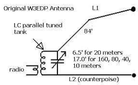
A description of the W3EDP antenna entitled ‘An Unorthodox Antenna’ was published in the March 1936 edition of QST. The antenna described in the article was developed by H. G. Siegel (W3EDP) probably around 1934. The antenna is based on the original Zeppelin antenna but removes the requirement for open wire feed line (ladder line). W3EDP’s objective was to build a multi-band antenna and today the antenna is a favourite of many QRP operators because it is simple, compact to transport, easy to deploy and easy to repair in the field. When used in confined areas, it must be remembered that the radiating element is 84 feet in length, but this is minimised when deployed with a high pole or tree limb.
Components
Component | Description | Supplier (Link to item) | Alternatives |
Antenna Wire | Approx 105 feet (32m) | Thin, flexible wire | |
BNC Binding Post and plugs | One set | Available elsewhere | |
Small connector | 2 Bullet connectors | Small spade connectors | |
Heat shrink | Heat shrink | Insulation tape | |
Cord | Approx 15 feet (5m) | String | |
Winder (optional) | Small | Various |
All the above links will take you directly to suitable items.
Tools required
Wire cutters
Wire strippers
Heat gun or cigarette lighter
Construction
- Cut three lengths of antenna wire; 84 feet, 10.5 feet and 6.5 feet long. The 84 foot length is the radiating element and the other two lengths form the counterpoise.
- Attach the RED banana plug to the 84 foot length: Strip about 1 inch of antenna wire and pass it through the hole in the prong of the banana plug. Twist it around the prong to secure it. I decided against soldering the connection as this can make the connection brittle. This method also allows for easier field repairs if needed. The boot of the banana plug was then fitted over the prong holding the antenna wire securely in place. Slide a short length of heat shrink tube over the other end of the 84 foot length, fold the wire back on itself and heat the shrink to form a secure loop. Attach the length of cord to this loop. This will be used to secure the antenna when deployed.
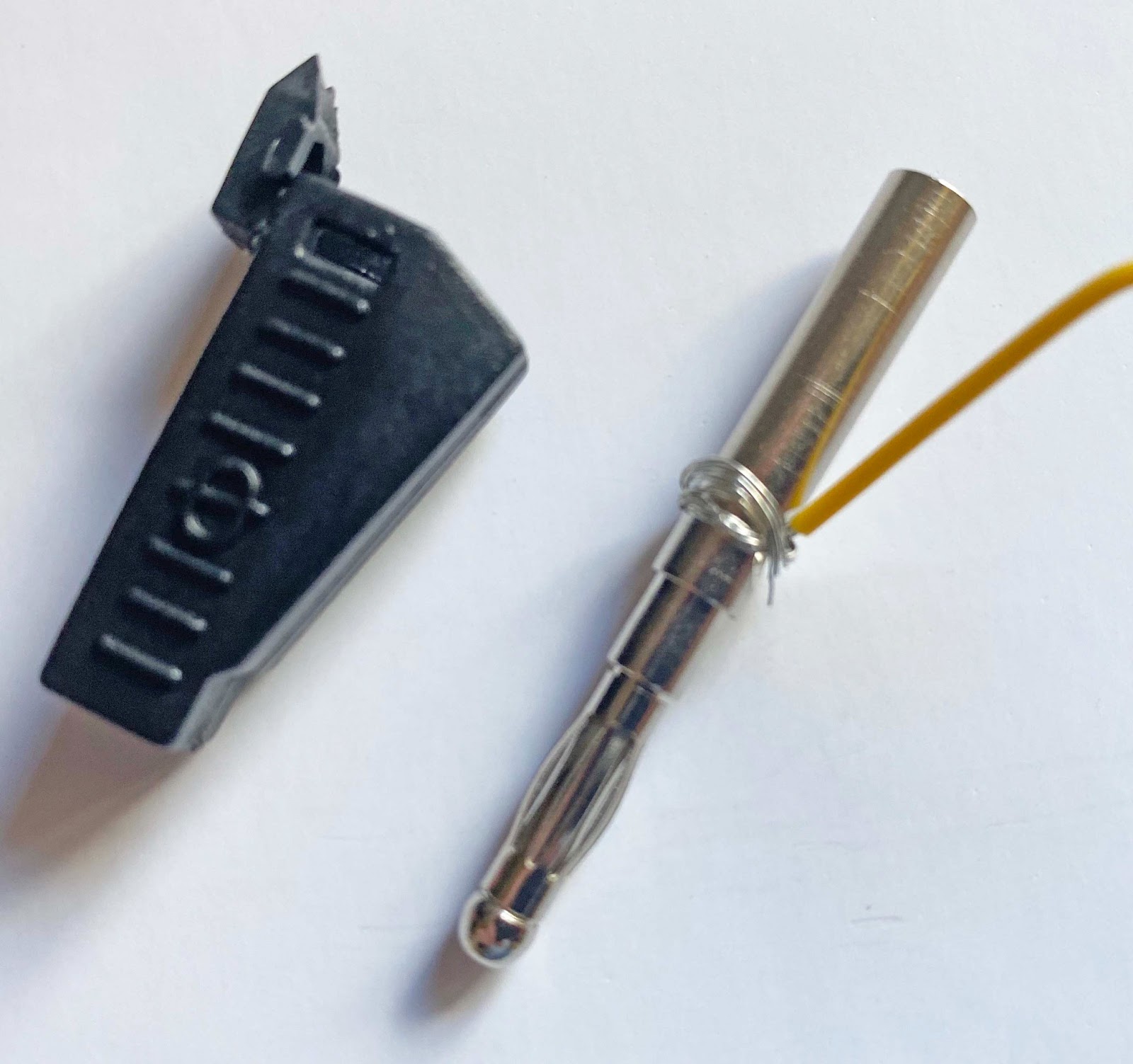
Image showing antenna wire wrapped around banana plug before boot is fitted.
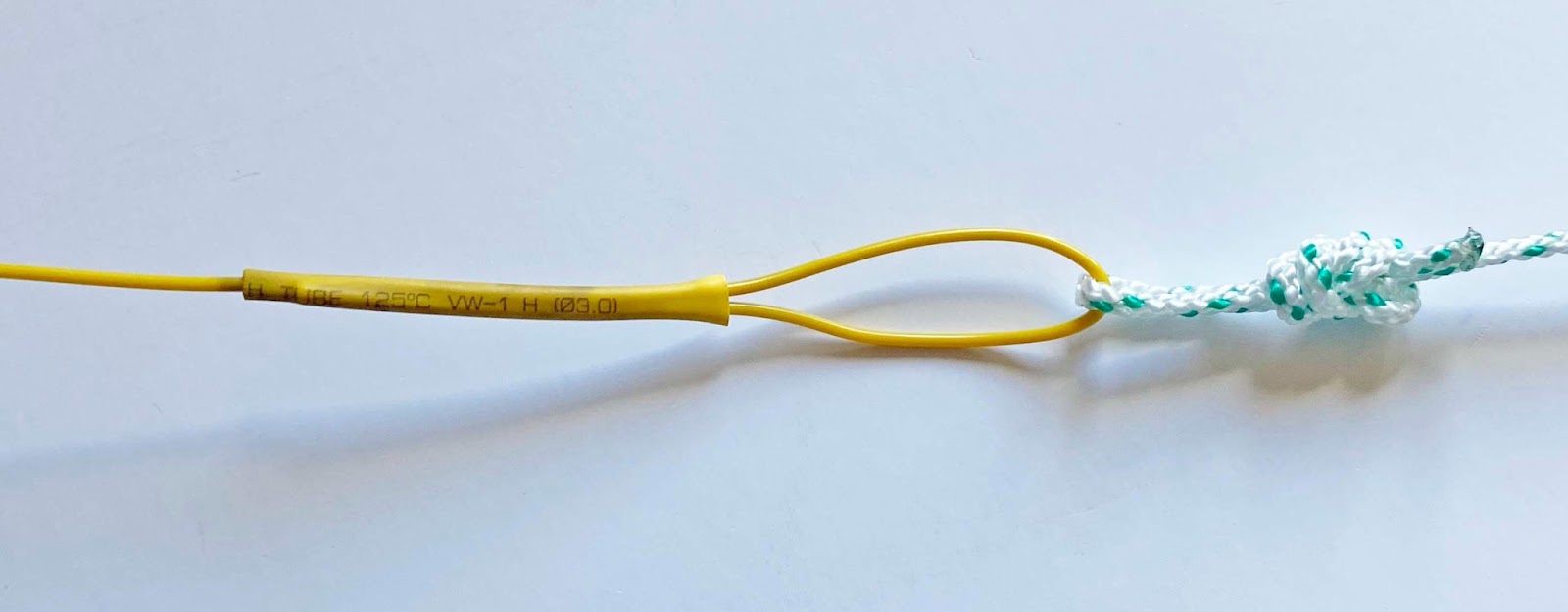
Image showing cord attached to end of 84 length of radiating element.
- Repeat the process to fit the BLACK banana plug to the 6.5 foot long length of antenna wire.
- Cut 2 x 1 inch pieces of thin heat shrink tube and place them over the ends of the 6.5 foot length of counterpoise and the 10.5 foot length of counterpoise. Pass a short length of cord through both pieces of heat shrink. Adjust and shrink into place. This will form some strain relief and will also keep the two parts of the counterpoise together. Fit bullet connectors to the end of the two pieces of counterpoise and crimp in place. Small electrical ‘spade’ connectors can be used here instead of bullet connectors. The counterpoise can now be linked or unlinked as needed.
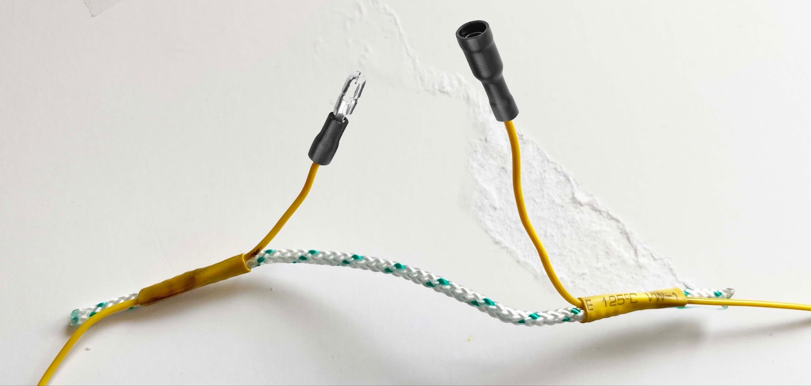
Image showing the two lengths of the counterpoise attached.
Diagram
Deployment
The BNC binding post should be fitted directly to the HF antenna socket of the tuner. (A adaptor may be required from SO239 to BNC female). NO COAX IS REQUIRED. The red banana plug is plugged into the red BNC binding post and the black banana plug to the black BNC binding post. The counterpoise (black banana plug) can be laid along the ground. This will connect to the ground through conductivity and form the earth of the circuit of the antenna. Its direction in relation to the active antenna wire does not have a significant effect. The main antenna wire (red banana plug) can be deployed as an inverted V, inverted L or a sloper. No great height is needed, but the cord end of the antenna should be kept approximately 3 feet or more above ground and secured with the cord attached. As the radiating wire is quite long, unless a long pole or tree limb is used to raise the radiating element, it invariably becomes a shallow angle sloper and is therefore particularly suited to NVIS or Inter G use.
Bands
The antenna is designed for use on 80m, 60m, 40m, 20m, 17m, 15m, 12m, 10m and 6m. A good ATU will also tune it to 160m. When used on 20m, just the 6.5 feet of counterpoise is used to get a good match. All other bands require the other 10.5 feet of counterpoise to be connected, to make 17 feet in length. The antenna design has been tested on all bands and found to give a good match and results. If problems are found getting a match, a 9:1 UnUn can be used to lower the impedance of the antenna to a more manageable value. The LDG 9:1 UnUn is particularly suitable as it is small, lightweight and the wire connectors on the UnUn also accept the banana plugs of the antenna and counterpoise directly.
Storage
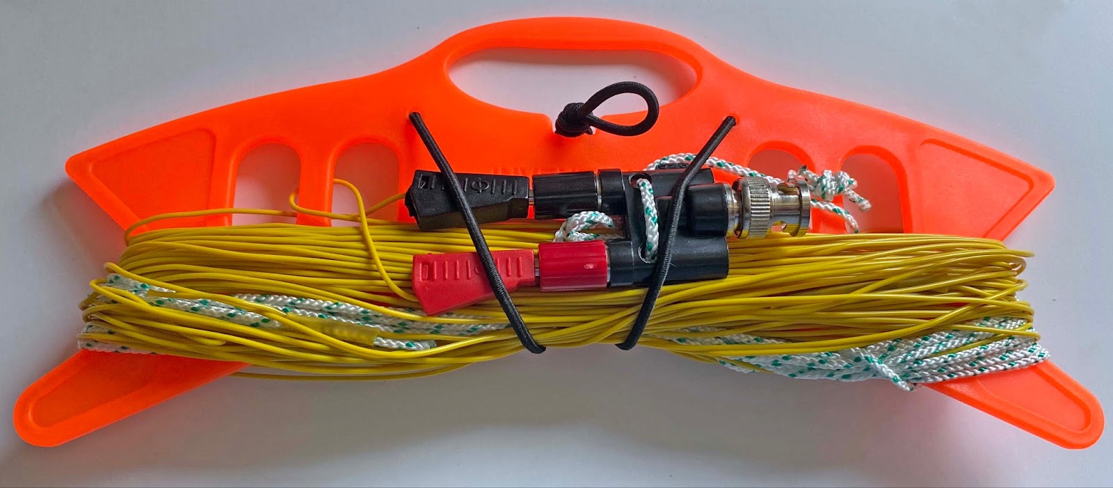
The antenna and counterpoise (linked) can be wound onto the winder and the BNC post attached. This is a compact and lightweight method of storing the antenna system.
Further information
Should you require any further information, this document was written by Richard (2M0NEG).