Computer Vision in Space
Maintenance of a 3D printed Martian Habitat through crack detection
AR2AA016 Interactive Architecture Prototyping
Team: Julka Lewandowska, Zeynep Yelken, Mikolaj Waszkiewicz & Henryk Gujda
Supervision: Seyran Kahdemi & Casper van Engelenburg (AiDAPT lab)
Contents
Model 3
Data 3
Introduction
Thanks to the efforts of multiple space agencies all over the World, the possibility of creating extraterrestrial habitats is slowly becoming a reality, first on the Moon as a test and then on the Red Planet - Mars. This enormous challenge will require experts from various branches of the Built Environment to get involved. The project, unlike on Earth, will require planning not only for the design and construction phase but also for safe and efficient maintenance predominantly for two reasons. Firstly, the conditions on Mars are unlivable due to a much weaker atmosphere with little oxygen, deadly solar and cosmic radiation, and temperature swings reaching down to negative 143 degrees Celsius. Therefore, the consequences of a structural failure on Mars are incomparably more deadly than on Earth. Secondly, the missions can take on a limited number of people with skill sets focused on researching the newly inhabited planet. Thus, employing the existing solution of certified structural inspectors is not viable in this context. There is a need for a specialised control system that will provide constant and thorough monitoring with little involvement from the mission’s crew.
Problem setting
Currently, one of the most widely considered construction technologies for building on Mars is 3D printing with concrete made out of Martian dust (regolith). The technology of 3D concrete printing (3DCP) is relatively new, yet develops rapidly in the context of Earth habitats, e.g. Project Milestone in Bosrijk, Eindhoven. The experience drawn from the existing prints, points towards potential cracking of the 3D printed construction. This creates a threat of structural failure also on Mars.
This project aims to provide a solution for a specialised control system that monitors the surface and detects cracks in a 3D concrete printed building envelope to provide maintenance and prevent a potential failure. To achieve this goal the project is going to implement computer vision. The inputs consist of images while the output provides the same image with information (a bounding box and a label) about the existence and location of a crack. In order to recreate the desired behaviour on Mars with Martian regolith concrete, the AI model is going to be tested using a set of images of cracks in regular 3D printed concrete since samples of regolith-based concrete have not been created yet.
Hypothesis / expectation
The research question can be phrased as “How can cracks in a 3D concrete printed structure be detected using computer vision?”. The expected outcome of this study is an AI computer vision model which detects cracks when provided with images and video footage of cracks in a 3DCP structure. The expected potential challenges are: inability of the model to differentiate between horizontal print lines and vertical cracks, model refusing to detect any cracks or line caused by too complicated wall surface and model requiring image preprocessing in order to detect cracks in 3DCP surfaces.
Methodology
In order to answer the research question an experiment has been set up. An existing model was selected and retrained on a dataset of cracks in regular concrete. A dataset of regular concrete was selected, because 3D printing technology is not advanced enough yet, and thus no large, reliable dataset of various cracks is available at this point. Therefore, training had to be conducted on images of regular concrete. The tests, however, were carried out using the limited, self-collected dataset of 3D printed samples to ensure that the model works also on the 3D printed surfaces.
Additionally, after the testing phase, the model was deployed on the web to operate in real-time and explore different accessibility options. This also enabled video inputs and allowed easier testing by various users and on various devices. Ideally, however, the model would be stored locally on a device responsible for crack detection, not accessed from the web, as the Internet connection on Mars is not yet established and might not be reliable enough, just like it is not entirely reliable on Earth. The aforementioned device, the rover, would be equipped with a camera that detects cracks utilising the CV model and a robotic arm that repairs them on site (Fig. 1).

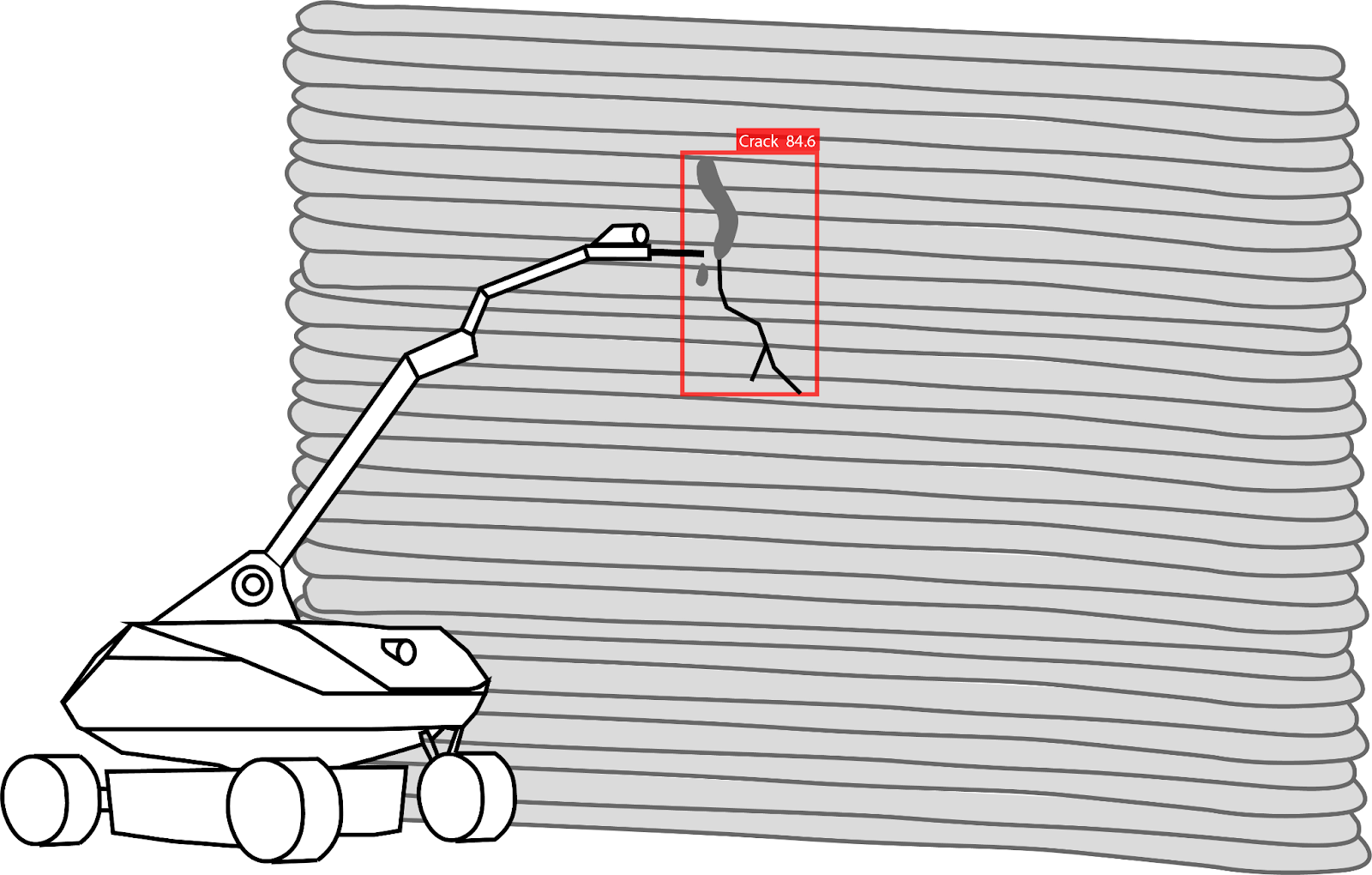
Figure 1. Potential application on Mars - detection and repair of the detected crack.
Model
The most fitting model for this application should be able to perform object detection. One of the best object detection models is YOLOv7. V7 is another, improved version of the original YOLO model which employs deep learning techniques, namely, convolutional neural networks (CNNs)(Kundu, 2023). CNNs are commonly used to analyse visual inputs and are capable of performing a variety of tasks from image segmentation to image generation. The YOLO model is specialised in object detection, therefore, fitting the objective of the experiment. The model will be downloaded from the developer’s GitHub repository (Fig. 2) and trained or, in fact, retrained on a custom dataset.

Figure 2. Source of the model.
Data
The dataset selected for the retraining is an Instance Segmentation dataset provided by Roboflow (Fig.3). It consists of approximately 4000 pictures of cracks in regular concrete out of which 3700 make up the training set, 200 images are the validation set and 112 - the testing set.

Figure 3. Dataset used in the project. Roboflow.
The images are preprocessed and annotated, and thus ready to be fed into the model (Fig. 4).

Figure 4. Example of an image from the dataset used for training. Roboflow.
The input provided to the model consists of clean images of cracks in concrete. The output from the trained model should consist of the same images, but with an added bounding box and a label to describe the detected crack, in this case the crack is also covered with a clipping mask (Fig. 5).
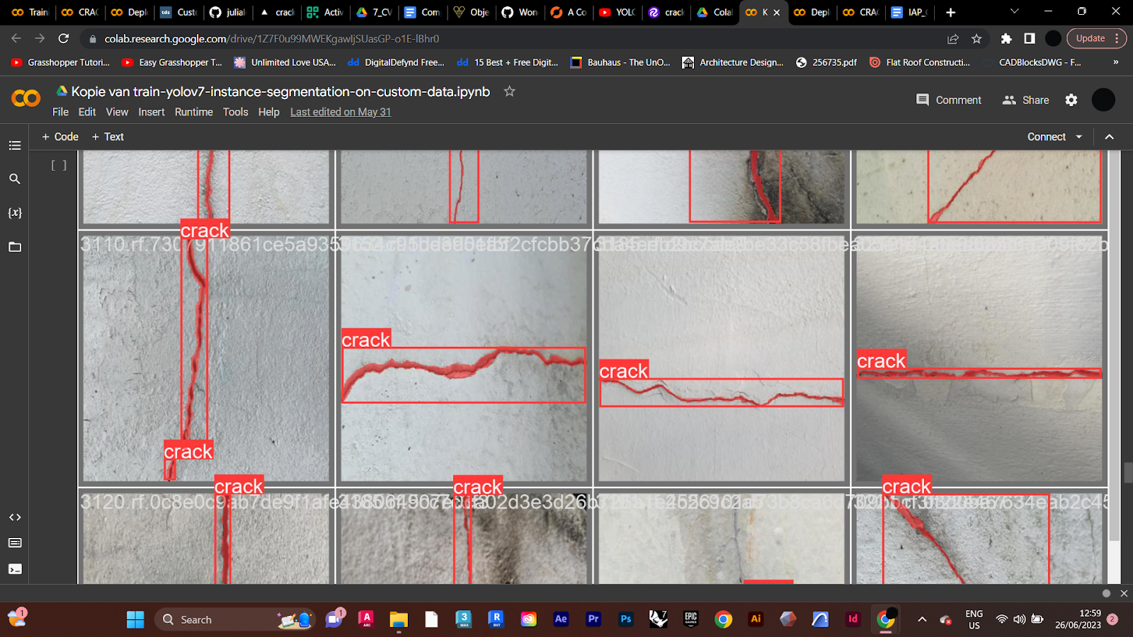
Figure 5. Example of the output from the model.
The dataset for training consists of images of cracks in regular concrete and was selected due to the unavailability of any dataset of cracks in 3D printed concrete. Thus, there was a need to create a new test dataset with images of 3D printed concrete (with and without cracks). This was done in order to evaluate the operation of the model on the material that it is actually aimed to work on, and yet, was not trained on.
The self-collected test dataset consists of 30 images of cracks in 3D printed concrete. The images are either collected from the Internet or taken at Vertico, a company specialised in 3D concrete printing. The test dataset is small, however, the deployment to the web aims to tackle that problem and enable testing in real-time whenever a new crack is observed.
Toolboxes and code
The first model, YOLOv7, was trained using a Roboflow Tutorial “How to Train YOLOv7 Instance Segmentation on a Custom Dataset” and the code provided with it (Skalski, 2022). The code of that tutorial is available in the notebook “Training YOLOv7_Roboflow code.ipynb”. The training process was evaluated for precision, recall and the mean average precision (mAP). The model which was created as a result of that training was downloaded and placed into another notebook, in which simplified code made testing easier. The code used for testing is available in the notebook “Testing trained model_rearanged Roboflow code.ipynb”. Then, the model was evaluated using the self-collected test dataset.
During research aimed at deploying the model on the web, it turned out that the model trained and evaluated so far was not appropriate. There is another version of YOLOv7 used for web applications, called YOLOv7 tiny. In result, another model, this time YOLOv7 tiny, was trained and evaluated in the same manner. Then, the model was converted to TensorFlow.js form to enable web application. Finally the js model was uploaded to a Git repository and deployed to the Internet through Vercel (available here: https://crack-detection-deploy.vercel.app/). The original code used for this part of the assignment was created by Hugo Zanini, a Google developer Expert in Machine Learning, and can be found in his article “Custom YOLOv7 Object Detection with TensorFlow.js” published in Towards Data Science (Zanini, 2023). The code, adjusted to the requirements of the assignment can be found in the notebook called “Training YOLOv7tiny and converting to TF.JS_Crack detection.ipynb”.
Experiments
The first evaluation conducted right after training, for both YOLOv7 and YOLOv7 tiny, considered the parameters of precision, recall and mean average precision. This evaluation aimed to determine to what extent the training process on the preselected dataset was successful.
Precision, the first parameter, shows the accuracy of the model by calculating the true positive guesses divided by true positives plus false positives. This way precision evaluates the correctness of the model's guesses (Fig. 6). (Hui, 2018)
Recall, the second parameter, determines how well does the model sieve out all the positive cases and how often does it miss. This is done by calculating the value of true positives divided by true positives plus false negatives (Fig. 6). (Hui, 2018)
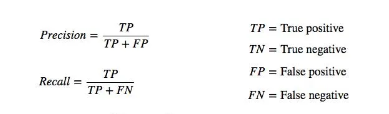
Figure 6. Mathematical definition of precision and recall. Jonathan Hui.
Finally, the third and the last parameter was the mean average precision (mAP). The mAP evaluates the accuracy of the model's detections by comparing the ground-truth bounding box and the detected box and to what extent these two overlap (Gad, 2020).
After this initial training evaluation, further testing and evaluation was conducted on a self collected dataset of 3D concrete printed samples. The dataset consisted of images of cracks in 3D concrete printed surfaces as well as the printed surfaces without cracks, to ensure that horizontal print lines are not detected as cracks. Further on in the research, after deployment on web, the dataset was widened with images of objects non-related to cracks in neither regular nor 3D printed concrete. This was done as thanks to the deployment the model became exposed to a much wider range of images and started producing interesting false positive outcomes.
Results and discussion
The evaluation of YOLOv7 and YOLOv7 tiny shows a very small difference in the outcomes of training of these two models. Precision of YOLOv7 after training reached approximately 0.7912 (Fig. 7) while for YOLOv7 tiny this parameter reached the value of 0.8461 (Fig. 8), thus YOLOv7 tiny should present less false positive guesses than YOLOv7.

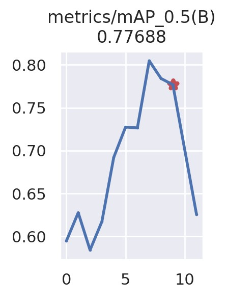
Figure 7. Precision, recall and mean average precision of the YOLOv7 model after training.
The opposite situation happened in cas of the recall parameter. In this category YOLOv7 scored approximately 0.7430 (Fig. 7) while YOLOv7 tiny reached only 0.7068 (Fig. 8). In result the YOLOv7 custom trained model should produce less false negative outcomes than YOLOv7 tiny.

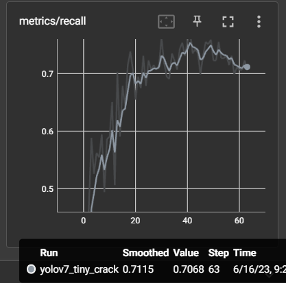

Figure 8. Precision, recall and mean average precision of the YOLOv7 tiny model after training.
Finally, the mean average precision of the YOLOv7 and YOLOv7 tiny turned out to be quite similar, reaching 0.7769 for the first one and 0.7848 for the latter. Hence, the accuracy of detected bounding box placement for both models is very similar and relatively precise compared to the ground-truth bounding boxes.
The evaluation of precision, recall and mAP shows the accuracy of the models when detecting cracks in regular concrete. What is, however, crucial for this application is the ability to detect cracks in 3DCP surfaces which differ in their texture from regular concrete. Thus, the next step of evaluation was testing the models ability to detect cracks in 3DCP sample images.
One of the first assumptions related to the challenges which would be faced when testing on 3DCP surfaces, was that the model would not be able to differentiate between the print lines of the concrete wall and the cracks and would detect printing lines as cracks (false positive). This claim was ruled out very early into the testing process, when it turned out that the models not even once would detect the print lines as cracks. The reason behind this is not entirely clear and leaves space for speculation. Firstly, the printing lines are much more regular in shape than cracks, therefore the model does not recognize them. Secondly, the contrast between shadows underneath the print layers and the surface of the wall is not as high as the contrast of a crack. The latter are usually darker making it easier to differentiate from print lines. Thirdly, the edges of cracks are sharper and more defined, while the print lines and their shadows are more diffused. Thus, the first expected challenge turned out not to cause issues (Fig. 9).

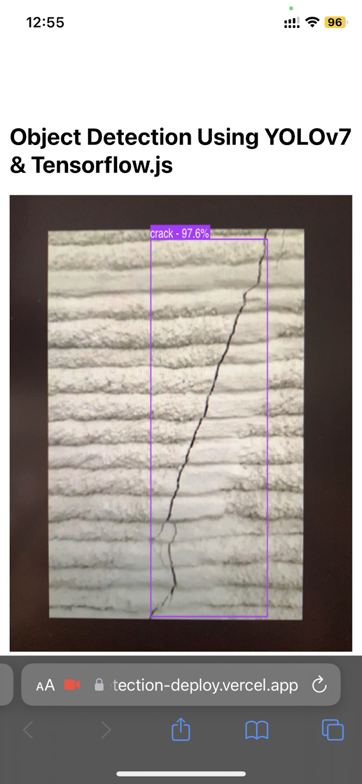
Figure 9. Successful crack detection on 3DCP surface using YOLOv7 (left) and YOLOv7 tiny (right) custom trained models.
A persisting problem, however, was related to the second assumption made at the beginning of the research. In some images the models would not detect any cracks even though the cracks were there (false negative). The suspected cause of this issue was again related to the printing lines which could create too much “noise” confusing the model and making it unable to work with the presented image (Fig. 10). The false negative outcomes were also more likely to appear as both models scored lower on recall than on precision, hence proving that they produce more false negative than false positive outcomes.
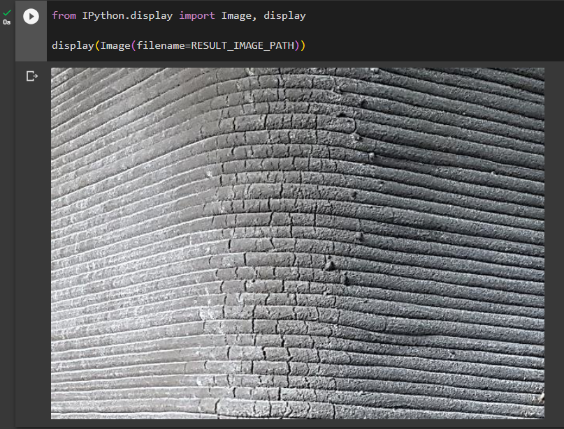
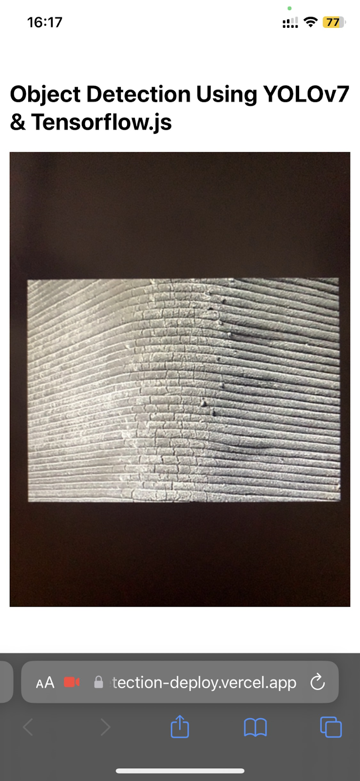
Figure 10. Unsuccessful crack detection on 3DCP surface using YOLOv7 (left) and YOLOv7 tiny (right) models.
It could be put into question if parameters of precision, recall and mAP generated for a dataset of regular concrete should still be considered in the context of detection on 3DCP surfaces. Nevertheless, in this case, they are considered, as the observed behaviour of the model does follow the prediction resulting from the evaluation based on the original dataset. What needs to be kept in mind, however, is that the reliability of these parameters will surely not be as good in case of the 3DCP dataset. Ideally, the 3DCP dataset should be made much larger, preprocessed and annotated in order to generate the parameters of precision, recall and mean average precision specifically for the 3DCP dataset rather than making assumptions regarding reliability of parameters generated for the original dataset. However, for now this was kept as a suggestion for future research improvement.
In order to solve the issue of false negative outcomes image preprocessing has been implemented. Considering that the cracks in 3DCP concrete always appear vertically and the print lines, which seem to cause the problem, are horizontal, a vertical motion blur has been applied to the images. The vertical blur aimed to smoothen out the print lines reducing the visual “noise” while still, to large extent, preserving the contrast between the crack and the wall surface and keeping the crack detectable (Fig. 11). However, this solution turned out not to be effective. The issue of false negative outcomes has not been solved. Furthermore, cracks which have been detected successfully in the past attempts, would be rendered undetectable when smoothened out with motion blur. This proved, however, that the irregular shape of a crack and its sharp edges, which would be lost after smoothing, are more important for the model’s operation than the contrast, which would be largely preserved despite image processing. The code to the motion blur image processing can be found in the notebook called “Image processing_motion blur.ipynb”.
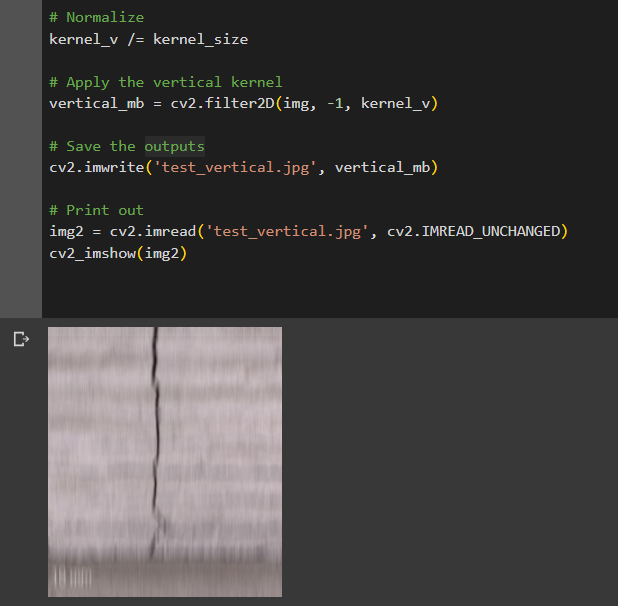
Figure 11. Test image processed with the motion blur.
The image processing solution, which brought end to the issue of false negative outcomes, was zooming into the image, so enlarging and cropping it. This still proves, however, that the print lines and their shadows may cause visual “noise” which makes it more difficult for the model to detect and recognize cracks. In figure 12 it can be observed that despite zooming in the detection is not entirely correct and there are still undetected cracks (false negative). This leads to two main conclusions regarding future development of the project. Firstly, the model which would be used for final application should definitely be trained on a dataset of cracks in 3DCP surfaces. This way the model will be prepared to detect cracks despite the shadows caused by printing layers and recognize the characteristic, fine crack pattern which can be seen in figures 10 and 12. Secondly, the Martian detection rover should be equipped not only with a camera for real-time detection but also with a light which would be flashed onto the 3DCP surface reducing the shadows and optimising the detection process.
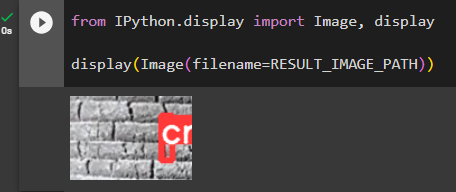

Figure 12. Zoomed in images with detected cracks from YOLOv7 (left) and YOLOv7 tiny (right).
Deployment to the web enabled also easier testing and observation of models’ behaviour on surfaces which were not part of the intended testing dataset. This revealed certain strengths and weaknesses in the operation of the models.

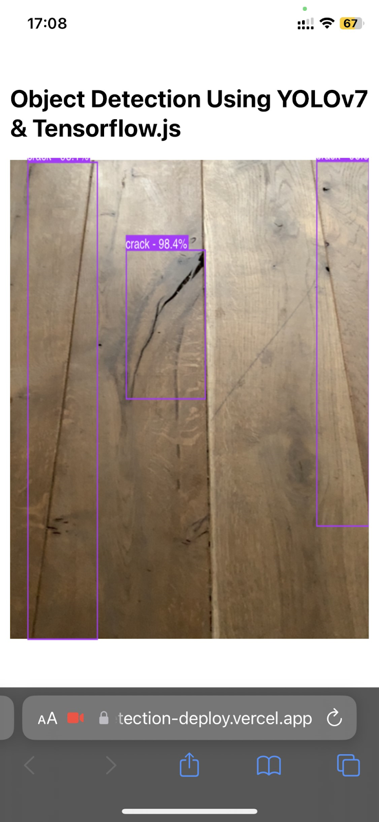
Figure 13. Crack detection on images other than the test dataset - YOLOv7 (left) and YOLOv7 tiny (right).
Firstly, the cracks seem to be detected not only in concrete but also in other materials like wood (Fig. 13). Although one of the “cracks” detected by YOLOv7 in figure 13 is only a scratch, its sharp edges and contrast against lighter background made it seem like a crack to the YOLOv7 model.
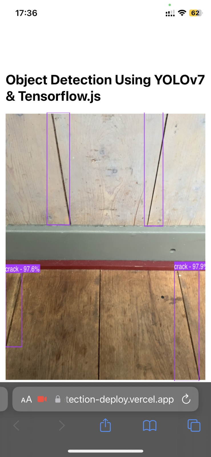

Figure 14. Crack detection on images other than the test dataset by YOLOv7 tiny.
Secondly, the number of false positive outcomes is very high, however the detected objects still satisfy the main characteristics of cracks. The gaps in between wooden floor and wall panelings as well as between the drawers are much darker than its surroundings and have sharp edges, therefore following the main characteristics of a typical crack in a concrete surface (Fig. 14). What is however rather surprising is the regularity in shape of the detected objects. The straightness of the detected lines seems to indicate that the typical, irregular crack shape is not one of the features considered by the model. This contradicts the previous conclusions where regular shape, lower contrast against the background and diffused edges were determined as the main reasons why print lines of the 3DCP surfaces are not detected as cracks. Thus, it seems that the regularity of shape does not play a role in crack detection and the main aspects influencing the detection are contrast and sharpness or diffusion of the edges.


Figure 15. Crack detection on images other than the test dataset by YOLOv7 tiny.
Moreover, the contrast requires the crack to be darker than its surroundings in order to be detected. The crack in the dark wooden counter surface or the long, light scratch on the wooden door are not detected as cracks despite their sharp edges and contrasting colour. This is because they are lighter than its surroundings, and therefore opposite to the models’ training datasets. The claim is further proven to be true, by colour inverting the images. Cracks turn darker than their surroundings and become detectable to the model (Fig. 16). Therefore, an object, in order to be detected as a crack, needs to have sharp edges, has to contrast against its background and be darker than its surroundings.
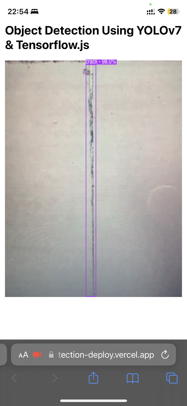
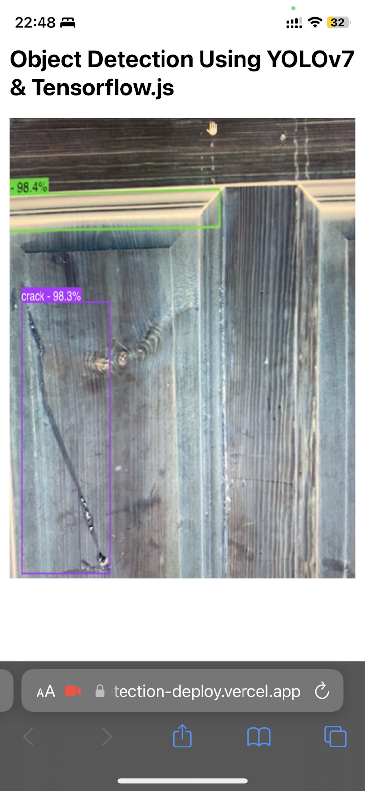
Figure 16. Crack detection on colour inverted images by YOLOv7 tiny.
Finally, brick surfaces do not seem to cause false positive outcomes. This might be caused by lack of objects with explicit crack-like characteristics which have been previously identified. Another reason could be related to the intense visual “noise” resulting from the variety of colours and textures brought into the image by bricks.
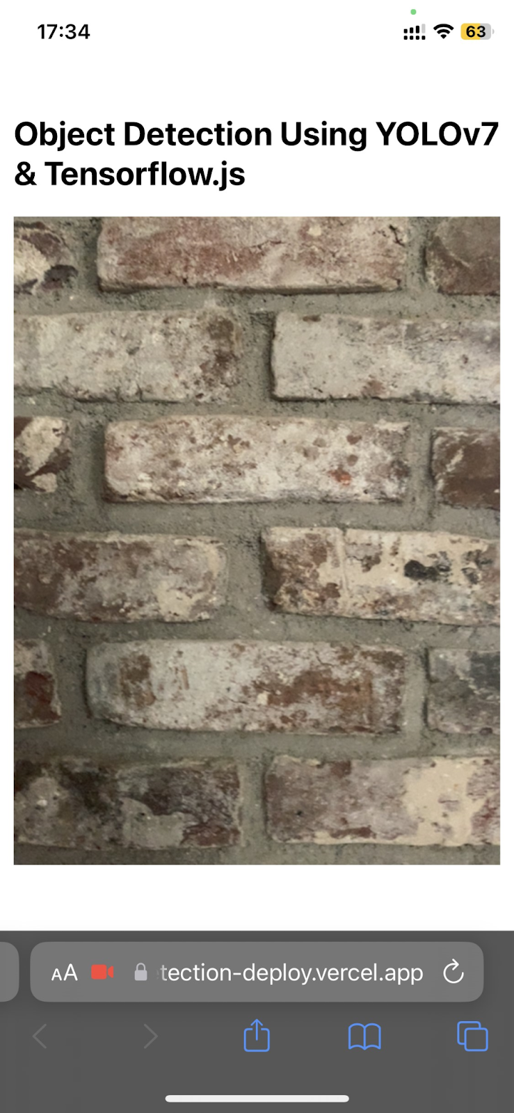

Figure 17. Crack detection on images other than the test dataset by YOLOv7 tiny.
Generally, certain detection problems might be a consequence of common issues typical for YOLOv7 and YOLOv7 tiny.
Firstly, YOLOv7 may struggle detecting objects which are small or are placed in a “crowded scene” (Kundu, 2023). This issue could be observed in case of the false negative outcomes, where zooming into the image allowed the model to detect cracks by enlarging the object and reducing the visual “noise” surrounding it.
Secondly, YOLOv7’s detecting abilities to a large extent depend on the environmental conditions, especially lighting (Kundu, 2023). This is also one of the main reasons behind the suggestion to equip the detecting rover with a light to illuminate the scanned surfaces. Although the testing process so far proved that shadows do not pose too large of a threat on the models detecting abilities due to their diffused character, the additional lighting would be of use and could rule out most of the false positive or false negative outcomes caused by wrong environmental conditions.
Lastly, the amount of computation required for YOLOv7 to operate may cause difficulties when run in real-time (Kundu, 2023). This is why a lighter and faster version of YOLOv7 has been chosen for the web deployment. The real-time application, however, still does not always run smoothly causing flickering of bounding boxes or false negative outcomes, impairing the ability of the model to successfully and accurately detect cracks.
Nevertheless, issues caused by the original model itself, are not the only source of challenges regarding the operation of retrained models. What plays a key role in this matter are the custom training process and the selected dataset.
The custom training process was in this case entirely based on the already existing code. In the case of the YOLOv7 model, the training was carried out on the exact dataset intended to be used by the author of the script. Thus, parameters like anchor boxes which need to be assigned depending on the application of the model and size of the detected objects, have already been adjusted to the specific requirements of the case. On the other hand, the parameters in the YOLOv7 tiny training code have been originally prepared for detection of empty supermarket shelves, hence might not be entirely fitting the new application of the code. Similarly, the number of training epochs was purely based on the preexisting code and could be readjusted for training optimization.
Moreover, custom training of the models on an actual dataset of cracks in 3DCP surfaces instead of regular concrete could further improve the operation of the models. However, collection and annotation of a 3DCP dataset as large as the one used in this project would be very challenging especially considering the scarcity of sources of 3DCP images. The dataset could also be generated artificially. Generating approximately 4000 images is still quite a challenge, but could be considered as a more realistic, potential future development idea than collection of real images. Training on generated images, however, poses a threat of creating a model which does not operate accurately on real images of cracks. Therefore, together with image generation, action must be taken towards making a reliable test dataset based on real-life images. This could also be done separately from the dataset generation, simply as another step in the project development. Creation of a reliable, annotated test dataset of 3DCP surfaces could allow for an evaluation of precision, recall and mean average precision similar to the one done for the regular concrete dataset, creating a possibility to accurately compare performance of the models on regular and 3DCP concrete.
References and Appendix
Gad, A. F. (2020). Evaluating Object Detection Models Using Mean Average Precision (mAP). Paperspace. https://blog.paperspace.com/mean-average-precision/
Hui, J. (2018, March 7). mAP (mean Average Precision) for Object Detection. Medium. https://jonathan-hui.medium.com/map-mean-average-precision-for-object-detection-45c121a31173
Kundu, R. (2023, January 17). YOLO: Algorithm for Object Detection Explained [+Examples]. V7Labs. https://www.v7labs.com/blog/yolo-object-detection
Roboflow (2022) Crack Computer Vision Project. https://universe.roboflow.com/university-bswxt/crack-bphdr
Skalski, P. (2022, December 29). How to train YOLOv7 Instance Segmentation on a Custom Dataset. Roboflow. https://blog.roboflow.com/train-yolov7-instance-segmentation-on-custom-data/
Zanini, H. (2023, March 28). Custom YOLOv7 Object Detection with TensorFlow.js. Towards Data Science.https://towardsdatascience.com/training-a-custom-yolov7-in-pytorch-and-running-it-directly-in-the-browser-with-tensorflow-js-96a5ecd7a530