How To Create
An
Ethernet Cable
Neil Domingo
BTech in Computer Systems Technology
New York City College Of Technology, CUNY
This user manual was created as a class project in ENG2575, OL88, Spring 2021. Any questions about this project should addressed to Neil Domingo at neilarthur.domingo@mail.citytech.cuny.edu
Table of Contents
2.1 Illustration of the Equipment
2.2 Description of the Equipment's Parts
3.0 List of Materials and Equipment Needed
3.1 Illustration of the Parts Needed to Carry Out the Instructions
3.2 Tools needed to complete assembly
3.3 Table of the parts with description of each
4.1 Assembling the Ethernet Cable
4.1.1 Gather the parts needed to assemble the ethernet.
4.1.3 Straighten and order the wires
4.1.4 Cut the wires in a straight cut
4.1.5 Place the wires into the RJ45 connectors
4.1.6 Crimp the cable using the crimping tool
4.1.7 Repeat steps 4.1.1 - 4.1.6 for the other end of the cable
4.1.8 Test the completed cable
1.0 Introduction
This instruction manual's focus is to instruct how to create an ethernet cable. I have created an ethernet cable in one of my classes. I used an ethernet cable to ping from one computer to another. An ethernet cable is used to connect an "electronic device (computer, tablet, gaming console, etc.) to a network, which, in turn, will allow you to have internet access and interact with shared network resources." [1]
1.1 Purpose
The purpose of this instruction manual is to assist a person in building their knowledge in the growing technology-based society. For those that are into technology, one can add this to their knowledge.
1.2 Intended Audience
This instruction manual is intended to those that are in the Information Technology (I.T.) field or are interested in technology. They can practice making ethernet cables and may benefit for future use. There is little to no knowledge needed for this manual as instructions will be given.
1.3 Scope
This instruction manual aims to instruct a person who is considered a "novice" in putting a working ethernet cable together. This instruction manual will take the reader in the step-by-step process on how to build an ethernet cable. In this manual, the reader will understand how to create an ethernet cable using an unshielded twisted pair Cat 5e cable and RJ-45 connectors. Then, testing the cables to make sure they work.
1.4 Organization Description
The following sections will include the motivation as to why one may want to to create an ethernet cable followed by a step-by-step process of assembling it, and troubleshooting any problems in the process.
1.5 Conventions
UTP - Unshielded Twisted Pair
RJ - Registered Jack
1.6 Motivation
This instruction manual is to inform others such as fellow students or peers in creating an ethernet cable. I have created an ethernet cable before and would like to share my knowledge. If one needs a new or backup ethernet cable, one can make it themselves. One can use this manual to create custom length ethernet cables.
1.7 Safety and Disclaimers
Please be careful when handling the crimping tool (will be shown later on in the manual). Please cautiously keep your fingers away from the blade when in use.
2.0 Description of Equipment
2.1 Illustration of the Equipment
1
2

3
4
2.2 Description of the Equipment's Parts
Equipment's Parts
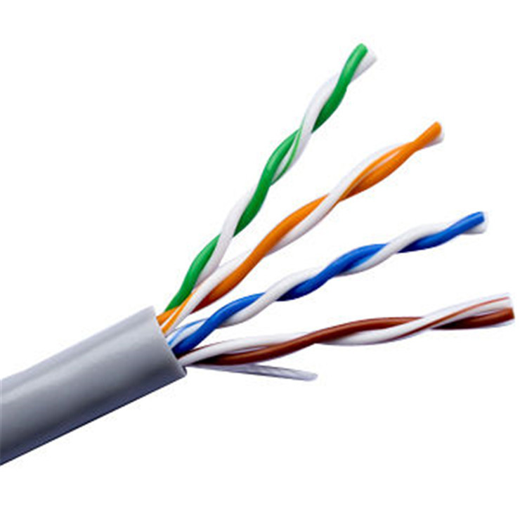
- A UTP cable (Cat5e is used in this manual)
- Crimping Tool
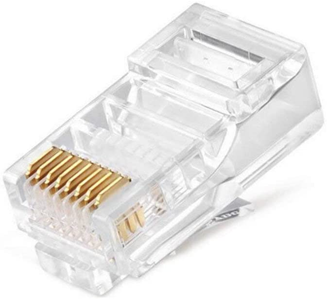
- RJ45 connector
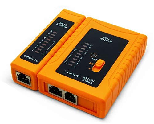
- Cable Tester
3.0 List of Materials and Equipment Needed
3.1 Illustration of the Parts Needed to Carry Out the Instructions
Same parts are used as shown in Section 2.0 - 2.2.
3.2 Tools needed to complete assembly
Again, the same parts/equipment shown in Section 2.0 - 2.2 are used to complete assembly.
All of the parts/equipment must be purchased in order to create an ethernet cable.
3.3 Table of the parts with description of each
Unshielded Twisted Pair (UTP) cable | This cable is a commonly used cable in computer networking and is mostly used for Local Area Networks (LAN). There are different UTP cable types such as the Cat 5e. |
Crimping tool | A tool that is used to crimp the RJ45 connector to the end of the cable once the wires are inside the connector. The crimping tool can also be used to strip the cable covering to expose the wires. |
RJ45 Connector | An RJ45 connector is a type of connector used for ethernet working. This is where the wires are inserted into in a certain order depending on the TIA/EIA standard. |
Cable tester | The cables that are created are inserted into the cable tester to test if the cable is working or which parts of the cable is not working. |
4.0 Directions
4.1 Assembling the Ethernet Cable
4.1.1 Gather the parts needed to assemble the ethernet.
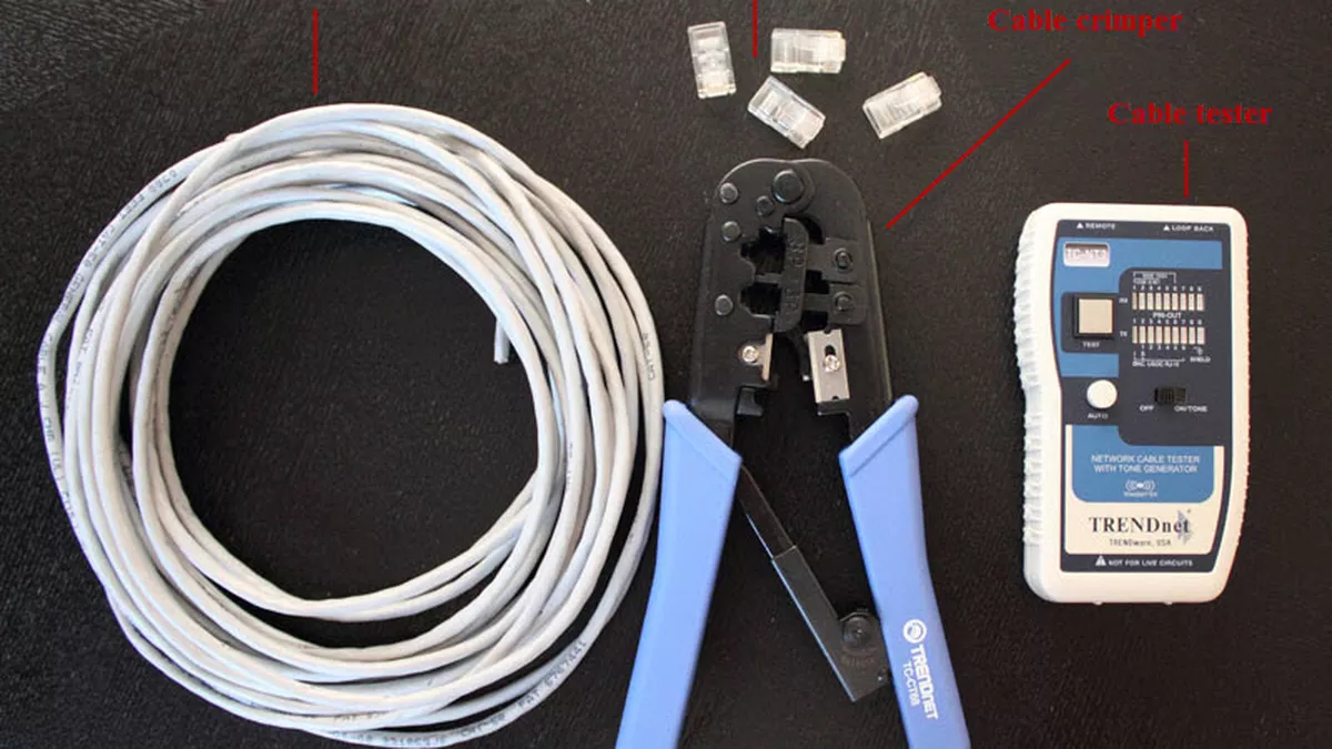
Image from Cnet
Similarly to the photo above, gather all the tools needed.
Any UTP cable (Cat 5e or Cat 6, depending on preference) can be used but I have only used a Cat 5e cable. All parts/equipment such as the UTP cable, crimping tool, RJ45 connectors, and cable tester were provided by my professor.
4.1.2 Strip the UTP cable
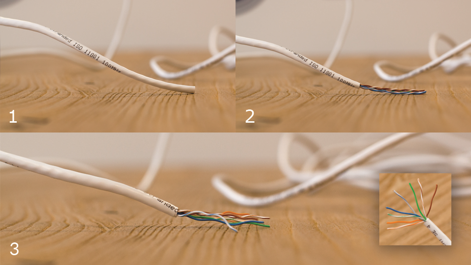
Image from Bascom
Use the sharp blade of the crimping tool and place the cable to cut the cover. Press the crimping tool onto the cover of the cable. Press down lightly and twist the cable to slowly remove the cover. Ideally, 1 - 1.5 inches of the wire should be exposed.
4.1.3 Straighten and order the wires
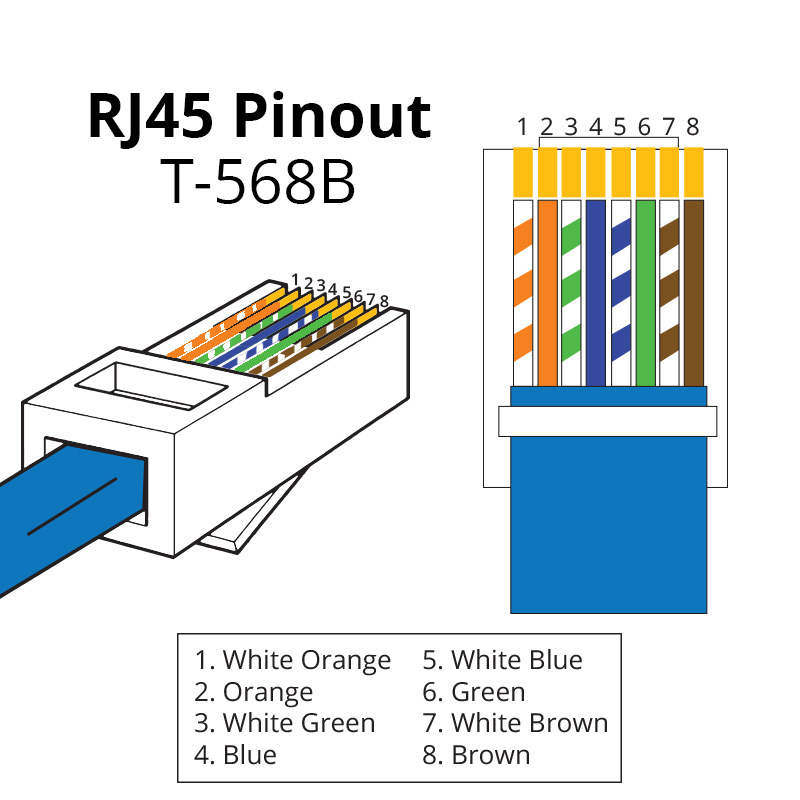
Image from Show Me Cables
The wires should be straightened and ordered based on the standard being used. In this case, the TIA/EIA standard of T-568B is used as it is commonly used in homes and businesses.
4.1.4 Cut the wires in a straight cut
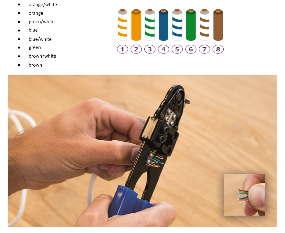
Image from Bascom
The wires must be cut in a straight line. They must be as even as possible and try to cut the wires in one try to avoid wasting the wire. Less than an inch (ideally .5 inches) of the wire should be cut to be straight as possible. The more wire, the better.
4.1.5 Place the wires into the RJ45 connectors
Image from Show Me Cables
Use this diagram to place the ordered wire into the connector.
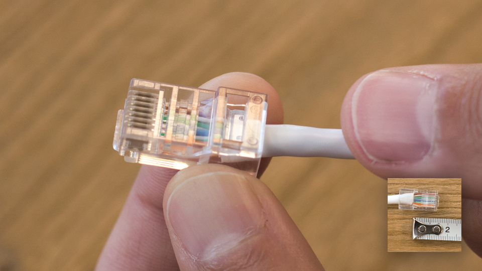
Image from Bascom
Make sure the connector's clip is facing down. Use the diagram above for reference Then, slowly insert the wires into the connector with each wire being as straight as possible. Each wire must be inserted into the correct corresponding pin. As shown in the diagram above, each pin is numbered from 1-8 with each pin having its own color.
4.1.6 Crimp the cable using the crimping tool
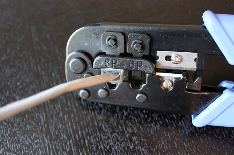
Image from Cnet
Place the RJ45 connector with the color coordinated wire into the crimping tool. Then, squeeze down the crimping tool. This would hold the wires in place and should be clamped to the copper inside the connector. The wires should not be pulled out of place.
4.1.7 Repeat steps 4.1.1 - 4.1.6 for the other end of the cable
Replicate the previous steps to the other end of the cable as close as possible.
4.1.8 Test the completed cable
Using the cable tester place both ends of the cable inside the slots.
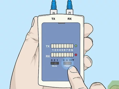
Image from WikiHow
As shown in this diagram, both ends of the cable are inserted into the tester. Turn on the tester. The tester will test each pin (1-8) of the cable. Disregard the G on the tester. Each pin must light up to ensure that the cable is working. If a pin does not light up, the cable is no good.
5.0 Troubleshooting
5.1 Cable is not working?
If a cable is not working, it is best to test it first using the cable tester before using the cable. If a pin does not light up on the cable tester, either a wire is not connected correctly, or the cable is damaged. Once a connector has been crimped, it cannot be used again. The cable may have been damaged, whether it is bent, has kinks, or rips. Also, make sure that the wires were correctly inserted in the color order according to the standard, in this case, T-568B. Make sure the cable was plugged in all the way. It is recommended to start over, utilizing a minimal amount of the cable when making a new one.
6.0 Glossary
[In order of appearance]
Ping | A signal sent from a computer to a host such as another computer, it will request a response. A ping is used in the command line interface to determine if the host is available and how long it took for the response. [2] |
Novice | A person that is inexperienced or new to a field. Also can be called a beginner. |
Cat 5e | One of the gigabit ethernets under the Cat 5 standard. It is a higher grade version of a Cat 5 wiring. It supports up to 1000 Mbps (throughput) and 350 MHz (bandwidth). |
RJ45 | A registered jack is a physical network interface that is used to connect telecommunications or data equipment. An RJ45 is commonly used to connect computers on Ethernet-based local area networks. [3] |
T-568B | One of TIA/EIA methods of inserting twisted pair wires into RJ45 connectors. More commonly used in homes or businesses. |
Kink | Twist or curl in something that is usually straight. |
7.0 Reference list
- FireFold. (n.d.). What Is an Ethernet Cable? Retrieved 2021, Apr 25, from https://www.firefold.com/blogs/news/what-is-an-ethernet-cable.
- Christensson, P. (2018, August 15). Ping Definition. Retrieved 2021, Apr 25, from https://techterms.com
- Anixter. (n.d.). What is an RJ45 Connector? Retrieved 2021, April 25, from https://www.anixter.com/en_au/resources/literature/techbriefs/what-is-an-rj45-connector.html