Architected Futures | EATSv5 Workbench Model Simulator 2 | ||
Context | Technical Architecture | Page | |
Subject | EATS Simulator Addendum | Date | 28Sep2016 |

Contents
Vendor Specific Factories Provided 30
Client RTI Ambassadors (A1) 38
Client Federate Ambassadors (A2) 39
Service RTI Ambassadors (A3) 39
Service Federate Ambassadors (A4) 39
Metadata Management Notes 9/28/2016 47
Simulation & Modeling Notes 9/5/2015 48
Simulation & Modeling Notes 9/5/2015 43
Addendum 1
The purpose of this document is to describe a detail addendum to the primary EATS Simulator document with a revision to the design scheme.
Significant portions of the content of this document referencing the HLA specifications, upon which the EATS Simulation Facility is based, have been adopted, with permission, from IEEE Std 1516.2™-2010
The IEEE hereby grants a general, royalty-free license to copy, distribute, display, and make derivative works from this material, for noncommercial purposes, provided that any use of the material contains the following attribution: “Reprinted with permission from IEEE Std 1516.2™-2010.” The material may not be used for a commercial purpose without express written permission from the IEEE. Should a reader require additional information, contact the Manager, Standards Intellectual Property, IEEE Standards Association (stds-ipr@ieee.org).
Overview
Concept
EATS contains specifications defining systems. A portion of those specifications are static and descriptive. The simulation facility is a tool to perform dynamic analyses of the systems described in the AIR Repository. For standard components, or system elements derived from standard component types, this can be done with the use of standardized EATS simulation components. The design of the system also provides for custom extensions to be able to be integrated with the standard components to model custom functionality. The general model for the conceptual solution is shown in Figure 1.
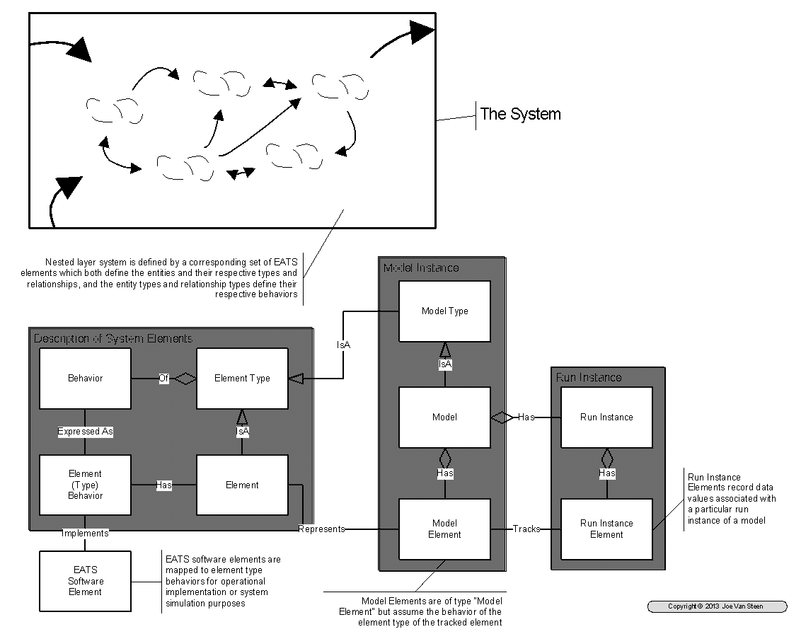
Figure 1 System Modeling Conceptual Framework
The box at the top of Figure 1 depicts a hypothetical system at some arbitrary level of specification. This system has relationships and interactions with other systems which are defined, for the purposes of the analysis study, to be out-of-scope. The bold arrows which interact with the bounding-box reflect these interactions. For the purpose of the study, they are considered exogenous elements and the interactions are viewed as interaction with "the environment." These elements, along with all of the other elements within the bounding-box are described in the AIR Repository by the entities in the blue box labeled Description of System Elements. These are the AIR Repository specifications that become the basis for the creation of a simulation model to examine the dynamic properties of the system.
The central blue box is labeled Model Instance and the right hand box is labeled Run Instance. The center box represents the simulation model and Run Instance represents the statistical and analytical product of running the simulation model. In Model Instance:
- Model Type defines the nature of the simulation model (System Dynamics, Discrete Event Simulation, etc.), Model Type is currently defaulted to EATS Behavior Model Type. However, this should be changed to a layered set of classes and types.
- Model is the construct which we create to execute the simulation, and
- Model Element defines the detail components of Model which stand-in for the individual, consequential system Elements defining the system in the AIR Repository specifications.
In the lower left is a component labeled EATS Software Element. This represents the standardized EATS software components, and potentially custom extensions, that create the dynamic view by emulating the behavior of the system in the course of the simulation.
HLA Framing
- Model Type might define FOM, SOM, or SOM/FOM. Each would be supported by an XML ObjectModel in the definition. FOMs organize and collect SOMs.
- FOM is a top level model, a federation
- SOM is a bottom level federate participant in a modeling process. These are candidates for inclusion in a FOM
- SOM/FOM is available as a SOM for participation in a FOM, but can also act, in the simulation, as a cascaded entity with additional SOM components to complete a simulated detail.
- Model is the FOM federation.
- Model Element is the SOM. SOM does not correspond to a single element in AIR, but the objects that make up the SOM each do. The SOM defines either specific Element/Objects to be assigned for representation in the model, or it defines Element Types which define objects and then defines some number of items of that type to be used for the model.
The EATS infrastructure is designed as a distributed, federated system. The software can be run as a single run unit on a single machine (node), but it can also be run as a distributed set of components spread over multiple machines. This allows multiple users to share, and/or interact through, components and data arranged on a network of machines. It also allows selected tasks to be placed on machines configured in some manner to handle the unique requirements of the task. The design philosophy of the simulator facility is to employ this same scheme of federated architecture.
HLA (High Level Architecture) defines an IEEE engineering standard (IEEE Std 1516) for the construction of federated simulation models which has been adopted for the construction of the EATS Simulation Facility. HLA defines a administrative scheme for managing a federation of processes conducting a coordinated simulation model. This includes rules about how the federated entities engage with each other, and descriptions of how they expose the objects, object characteristics and states, events and behaviors which occur during the simulations. But HLA is agnostic to what the objects and events of the simulation may be.
HLA Terminology
Basic Terms
base object model (BOM): A piece-part of a conceptual model, simulation object model (SOM), or federation object model (FOM) that can be used as a building block in the development and/or extension of a simulation or federation.
federation: A named set of federate applications and a common federation object model (FOM) that are used as a whole to achieve some specific objective.
federation execution: The actual operation, over time, of a set of joined federates that are interconnected by a runtime infrastructure (RTI).
federate: An application that may be or is currently coupled with other software applications under a federation object model (FOM) Document Data (FDD) and a runtime infrastructure (RTI). See also: federate application; joined federate.
federation object model (FOM): A specification defining the information exchanged at runtime to achieve a given set of federation objectives. This information includes object classes, object class attributes, interaction classes, interaction parameters, and other relevant information. The FOM is specified to the runtime infrastructure (RTI) using one or more FOM modules. The RTI assembles a FOM using these FOM modules and one Management Object Model (MOM) and Initialization Module (MIM), which is provided automatically by the RTI or, optionally, provided to the RTI when the federation execution is created.
federation object model (FOM) Document Data (FDD): The data and information in a FOM that are used by the Create Federation Execution service and successive Join Federation Execution service invocations to configure the federation execution.
federation object model (FOM) module: A partial FOM (containing some or all object model template (OMT) tables) that specifies a modular component of a FOM. A FOM module may contain classes not inherent to it but upon which the FOM module depends, i.e., superclasses to the modular components. These superclasses will be included in the FOM module as either complete or scaffolding definitions.
Management Object Model[1] (MOM): A group of predefined High Level Architecture (HLA) constructs (object and interaction classes) that provide the following: a) Access to federation execution operating information b) Insight into the operations of joined federates and the runtime infrastructure (RTI) c) Control of the functioning of the RTI, the federation execution, and the individual joined federates.
Management Object Model (MOM) and Initialization Module (MIM): A subset of the federation object model (FOM) that contains object model template (OMT) tables that describe the High Level Architecture (HLA) MOM. The MIM also contains additional predefined HLA constructs such as object and interaction roots, datatypes, transportation types, and dimensions. HLA specifies a standard MIM that is incorporated into all FOM Document Data (FDD) automatically by the runtime infrastructure (RTI). The standard MIM can be replaced with a user-supplied MIM containing the standard MIM plus extensions.
runtime infrastructure (RTI): The software that provides common interface services during a High Level Architecture (HLA) federation execution for synchronization and data exchange.
runtime infrastructure (RTI) initialization data (RID): RTI vendor-specific information needed to run an RTI. If required, an RID is supplied when an RTI is initialized.
simulation object model (SOM): A specification of the types of information that an individual federate could provide to High Level Architecture (HLA) federations as well as the information that an individual federate can receive from other federates in HLA federations. The SOM is specified using one or more SOM modules. The standard format in which SOMs are expressed facilitates determination of the suitability of federates for participation in a federation.
simulation object model (SOM) module: A subset of the SOM that contains some or all object model template (OMT) tables. SOM modules and one optional Management Object Model (MOM) and Initialization Module (MIM) are used to specify the SOM of a federate. A SOM module contains complete or scaffolding definitions for all object classes and interaction classes that are superclasses of object classes and interaction classes in the same SOM module.
HLA Operational Scheme
Federates are the software components that conduct the simulation. The collection of all federates defines a federation. Federates own and expose the objects describing the system components. Communications between federates describing the events and state of the simulation are communicated via interactions. A federate describes the objects and interactions it provides and/or requires in a simulation object model (SOM). The collections of all objects and interactions used within a federation is described in a federated object model (FOM). In addition to the consolidation of SOMs for the involved federates, a FOM also includes additional objects and interactions used in the management of the overall simulation, described as a management object model (MOM).
- FOM is defined by the element that defines the system being modeled.
- That element defines various components, and it defines environmental entities that are exogenous.
- Each of the components, and each of the exogenous elements is a federates with a SOM, defined by their own element type, and any behavior model which may exist.
- In addition, we want to be able to cascade, such that a behavior model might be a lower level simulation.
Model Definition
HLA provides two ways to describe and model the system (1) Objects, and (2) Interactions. These are shown in Figure 2. Any model could be implemented using either of these schemes. However, some concepts and operations are easier the conceptualize using one or the other. Together they provide greater flexibility to the modeling process.
Objects
HLA models are composed of a hierarchy of objects. These include the primary objects of the model, plus management objects defined in the MOM. Objects are types. In the operational model objects have instances defined by instance handles. In EATS, the HLA object hierarchy corresponds to a class hierarchy, extended to an element type, and then, potentially, an element instance of that type.
Objects define the system entities and their significant characteristics (attributes). Only the objects that are visible and of significance outside the scope of a federate need be defined (in the FOM and SOM) using the HLA mechanisms. Objects are defined using a hierarchical class structure where parent objects define generalized classes of things and child objects define refinements of the generalized class concept (e.g., trees/Elm trees; people/doctors/Neurosurgeons). Attributes defined for higher level objects (e.g., eye color for people) are inherited by and apply to all child classes (doctors and Neurosurgeons).
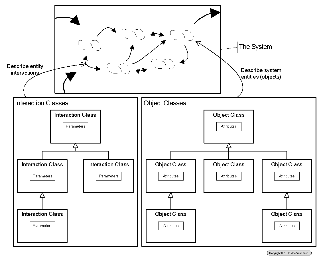
Figure 2 HLA Conceptual View
In HLA, objects have declared characteristics, defined as attributes. In EATS, elements (classes and types) also have declared characteristics, defined as attributes. Attributes tend to fall into the following groups:
- Definitional - these are attributes with fixed values which are used to define the type or identity of an instance.
- Static characteristics - these are attributes with fixed values which do not change through the life of the simulation.
- Dynamic characteristics - these are the attributes which change through the life of the simulation. These are the values which need to be communicated regularly to monitor state and the values which may need to be logged to be able to perform analyses after the simulation has been run. For these attributes we want to track:
- The identity of the attribute (owning instance and attribute instance identity)
- The time of change in value
- The new value at the specified time.
In some models objects may have only one or two dynamic characteristics of concern. In other models, there may be multiple continuously changing characteristics. Characteristics should be able to be packaged and communicated, or logged, in groups, such as:
- Identity of owning instance, time of change in value
- Attribute Instance Identity, new value
- Attribute instance identity, new value
Interactions
Interactions define collections of data sent at one time to communicate between the federated components of a simulation and their data content (parameters). They may represent events or changes in state within an object, or they may communicate any other information that has value in being shared between components. They provide a mechanism to encapsulate and describe the interactions that occur between objects managed and controlled within one federate with objects managed and controlled by one or more other federates. Interactions are also defined using a hierarchical class structure where parent interaction classes define generalized classes of communications and child interaction classes define refinements of the generalized communications concept (e.g., business transaction/purchase order; account setup/banking account/savings account). Parameters defined for higher level objects (e.g., customer on account setup) are inherited by and apply to all child classes (banking account and savings account).
The second major set of elements defined in HLA models is a hierarchy of interactions. These include the primary action set of the model based on the nature of interaction between the model objects, plus management interactions defined in the MOM[2]. Interactions are messages communicated by a federate. They may represent events and are a mechanism for communicating data, including changes in dynamic characteristics, that are of concern outside the internal operational concerns of the federate. Interactions are also defined using a hierarchical class structure. Interactions may be associated with a point in simulated time. In the same manner that object class are defined with attributes, interaction classes are defined to host parameters; and parameter inheritance is supported similar to attribute inheritance in objects. Parameters however are all static. They simply reflect a value at a point in time.
In EATS, the HLA interaction class hierarchy corresponds to an object class hierarchy of message types which implement activities within a dynamic relationship class hierarchy, extended to the various relationship element types. For example, EATS might define a "Company A maintains Policy B" relationship. "Company A" and "Policy B" are objects (entity elements). "Maintains" is a relationship between the two. Assuming "maintains" is defined as a dynamic relationship, a life-cycle detailing of "maintains" as implemented between a corporate entity and a policy may involve such activities as:
- Publication of the policy.
- Publication of modifications to the policy.
- Auditing corporate units for conformance to the policy.
Without becoming mired in the creation of a detailed model for the example, the occurrence of these activities as events would be announced by the "Company A" object to concerned observers via a message instance of a particular type at each occurrence. These message, in HLA terms, are interactions.
Each interaction is described by a message. The content of the message is specified by the parameter set defined for the interaction. Internal to the EATS Architected Space, interactions are carried as EATS Architected Messages. Federates operating within the EATS infrastructure encode and decode interactions using EATS internal information encoding (e.g., object serializations). On the boundary of EATS Architected Space, these messages are communicated via the IEEE 1516 specification. Boundary functions[3] are used to translate between these two physical formats.
HLA Processing Structure
The discussion above related primarily to the specification of metadata. Metadata describes the nature of things, but not the actual instances of things. For example, eyes have color, not John's eyes are blue. Running a simulation is a process of dealing with simulated instances of things that conform with general understandings of what those things are. This is shown in Figure 3. In that diagram the blue classes on the right reflect metadata, the pink classes on the left define instances. Discussions of processing are typically focused on instance data. The instance data defines the thing being modeled, or the action or event being communicated. The metadata described rules for behavior of the thing, and or structure, semantics and significance of things. The instance data is changeable and dynamic during the simulation; the metadata is constant.
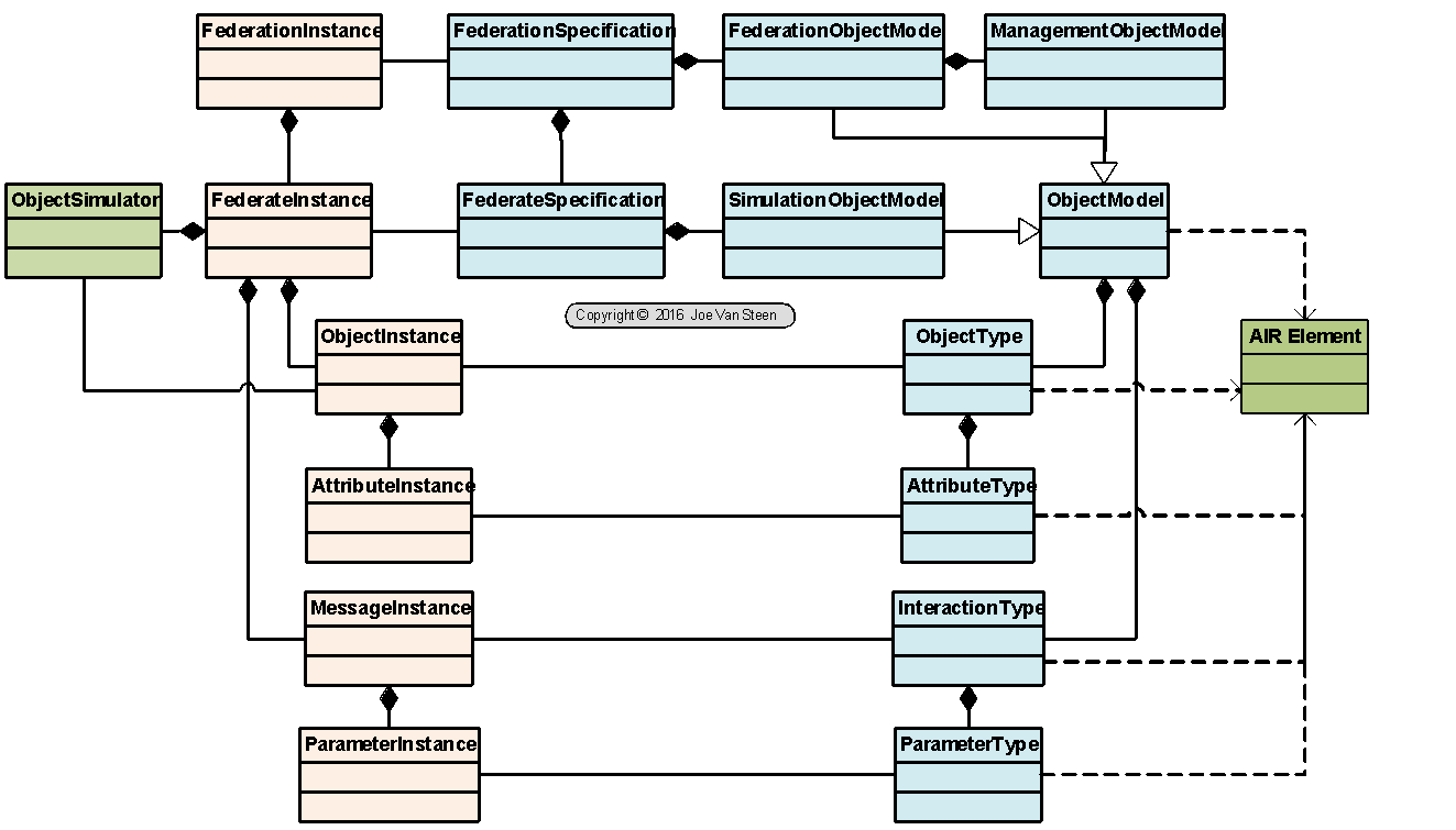
Figure 3 HLA Runtime Model
The rules for federations under the HLA standards are as follows:
- Federations shall have an HLA FOM, documented in accordance with the HLA OMT.
- In a federation, all simulation-associated object instance representation shall be in the federates, not in the RTI.
- During a federation execution, all exchange of FOM data among joined federates shall occur via the RTI.
- During a federation execution, joined federates shall interact with the RTI in accordance with the HLA interface specification.
- During a federation execution, an instance attribute shall be owned by at most one joined federate at any given time.
The rules for federates under the HLA standards are as follows:
- Federates shall have an HLA SOM, documented in accordance with the HLA OMT.
- Federates shall be able to update and/or reflect any instance attributes and send and/or receive interactions, as specified in their SOMs.
- Federates shall be able to transfer and/or accept ownership of instance attributes dynamically during a federation execution, as specified in their SOMs.
- Federates shall be able to vary the conditions (e.g., thresholds) under which they provide updates of instance attributes, as specified in their SOMs.
- Federates shall be able to manage local time in a way that will allow them to coordinate data exchange with other members of a federation.
The rules for construction of an HLA federation according to rule 3 require a "star-shaped" or "bus-based" communications architecture similar to that shown in Figure 4.
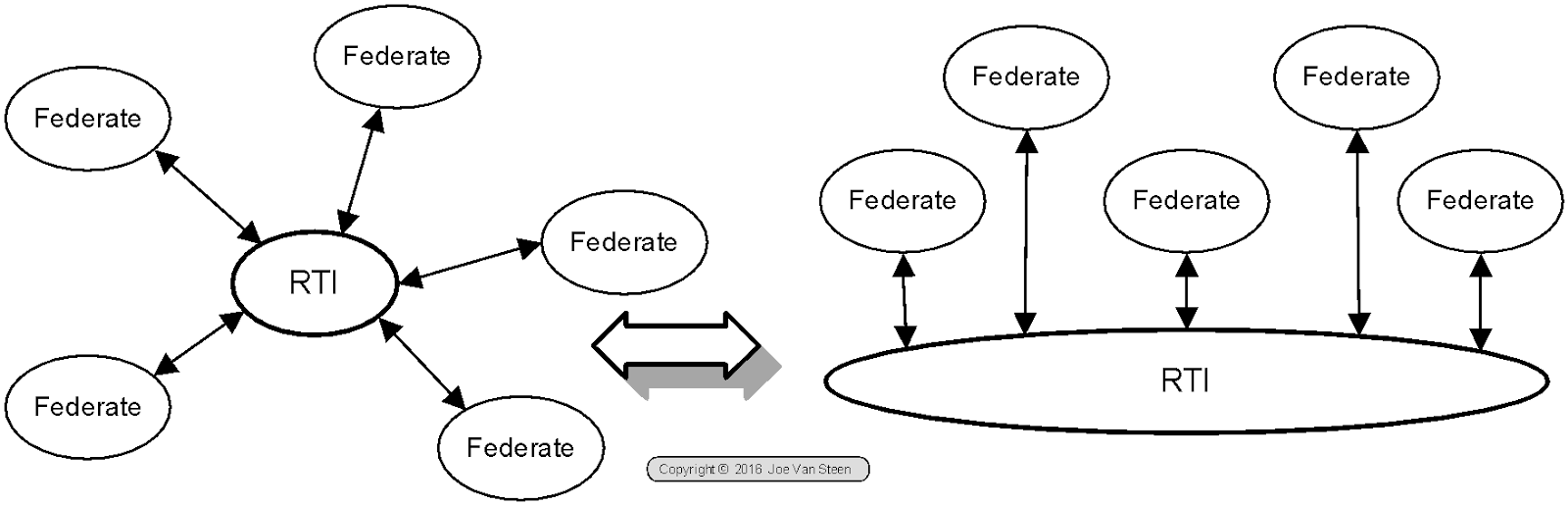
Figure 4 HLA Communications Architecture
In addition, the standards lay out a framework for the RTI-Federate interface using what are termed "ambassadors" as shown in Figure 5.
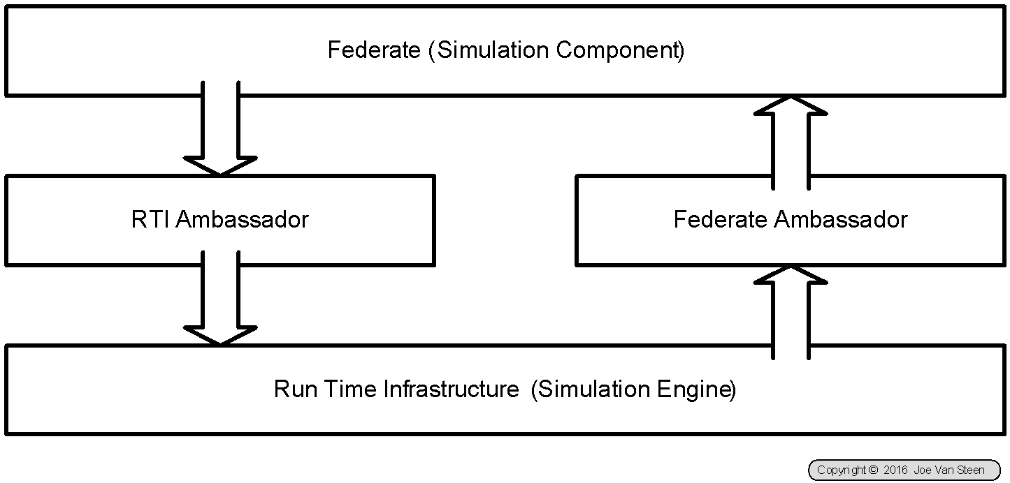
Figure 5 HLA Ambassador Framework
Given these rules and architectural framing we can create the following framing rules for the configuration of a simulation within EATS.
Based on Figure 4 HLA Communications Architecture:
- The RTI is the central component for configuration of a simulation federation.
- Any component the RTI has instantiated can communicate with the RTI and therefore can participate in the federation. This includes components on remote processing nodes.
- Any component that can locate and establish a communications path with the RTI can participate in federations managed by that RTI. This includes external clients of the processing node on which the RTI is executing.
The architecture of how to do this is indeterminate unless the RTI incorporates a front-end feature capable of mapping conversations - which will need to map both requests and responses. But then, this is
Based on Figure 5 HLA Ambassador Framework:
- Communication between the RTI and federates needs to be in conformance with the semantic significance of the communication, which may or may not be in conformance with the syntactical hierarchical pattern of the EATS communications infrastructure[4]. Mapping and unmapping the simulation semantics from the infrastructure syntax is the responsibility of the ambassador framework[5].
- Publish - What it means to publish. When a federate publishes a class it is allowed to own objects instances of the specified class. For every class a Federate wishes to register() or take ownership of it first must publish that class. Federates who would want to produces objects(instances of a class) need to register also. In general, any Federate who wants to produce or register objects must first publish the class.
- Subscribe - The RTI will notify any federate subscribed to class whenever there is an instance of the specified class.
- The RTI will starting notifying the federates that an instance of a class they have subscribed to is available by telling them to start registering for this class.
- Update - The Federate supplies new Attribute Values for an object it has registered for to the RTI.
- Reflect - The RTI will supply the Federate(s) that are subscribed to the object’s instance attributes. For each Update() there may be multiple reflect() service calls due to multiple federates being subscribed to the instance attribute.
Figure 6 CMU Wright Flyer Sample Object Management Use Case
This is a use case diagram showing the basic relationships between the major functions of the flyer and the major objects it needs to interact with. Note how the RTI is involved with all use cases -- this is because all interaction of the flyer with external objects must be done through HLA. The simulator client controls the creation and destruction of the flyer object hierarchy. The pilot actor actually controls the flyer by modifying control values. Finally, information from the environment is needed to calculate the updated flight position, which is then given to the UI to allow viewing.
Object Model Structure
HLA object and interaction models are described as single-inheritance hierarchical sets of elements. However, they are more accurately, from a programming perspective, viewed as containment models, where contained child elements inherit attributes from their "structure graph" parents.
IEEE 1516.2 specifies:
HLA object models are composed of a group of interrelated components specifying information about classes of objects and their attributes and interactions and their parameters. The information content of these components can be represented in many different ways or presentations. A presentation is the formatting of the information contained in the object model in a particular manner for a particular purpose. For example, the OMT tabular format is designed for presentation on a printed page, whereas the OMT data interchange format (DIF) is a presentation designed for passing an object model between tools. All HLA object models shall be capable of being presented in both the OMT tabular format and the OMT DIF format. This standard defines the OMT content and presents it in OMT tabular format throughout.
The OMT consists of the following components:
- Object model identification table: To associate important identifying information with the HLA object model
- Object class structure table: To record the namespace of all federate or federation object classes and to describe their class-subclass relationships
- Interaction class structure table: To record the namespace of all federate or federation interaction classes and to describe their class-subclass relationships
- Attribute table: To specify features of object attributes in a federate or federation
- Parameter table: To specify features of interaction parameters in a federate or federation
- Dimension table: To specify dimensions for filtering instance attributes and interactions
- Time representation table: To specify the representation of time values
- User-supplied tag table: To specify the representation of tags used in HLA services
- Synchronization table: To specify representation and datatypes used in HLA synchronization services
- Transportation type table: To describe the transportation mechanisms used
- Update rate table: To specify update rate information
- Switches table: To specify initial settings for parameters used by the RTI
- Datatype tables: To specify details of data representation in the object model
- Notes table: To expand explanations of any OMT table item
- Interface specification services usage table: To specify the HLA services used by a federate or in a federation
- FOM/SOM lexicon: To define all of the objects, attributes, interactions, and parameters used in the HLA object model
All of the OMT components shall be completed when specifying an HLA object model for both federations and individual federates. However, certain tables may be empty or devoid of domain-specific content. For instance, although federations typically support interactions among their federates, some federates (such as a stealth viewer) might not be involved in interactions. In this situation, the interaction class structure table would contain only the single interaction class required by the HLA and the parameter table would be empty in that federate’s SOM or supporting SOM module. It is also expected that federates commonly have objects with attributes of interest across the federation; in such cases, these objects and attributes shall be documented. However, a federate or an entire federation may exchange information solely via interactions; in which case, its object class structure table and attribute table would contain only HLA-required data. The specific rules for the applicability of each OMT table are provided in the table descriptions.
The final HLA OMT component, the FOM/SOM lexicon, is essential to help users understand the semantics of the terms used in an HLA object model.
The HLA MOM specifies a designated set of information elements that are associated with federation executions. Implementation of the MOM information elements as specified in IEEE Std 1516.1-2010 provides a mechanism for management of federation executions using existing HLA services. Inclusion of the MOM is required for all FOMs and is achieved by incorporating the MOM data using a MOM and MIM. In addition, federates that have an inherent capability to interact with or extend the MOM shall include the MOM in their SOM. Inclusion of the MOM means the inclusion of a MIM that contains all tables in Clause 11 of IEEE Std 1516.1-2010, along with any applicable MOM extensions.
The last row in any OMT table is labeled “Note.” This allows the object model developer to associate one or more notes with the entire table. If no note is being provided for that table, a value of “NA” should be entered. Although the “Note” row is not explicitly identified or discussed in the table descriptions, it is shown in the table examples for illustration purposes. The notes feature is fully explained in 4.14.
A FOM or SOM is specified using one or more FOM or SOM modules. For a FOM, a MIM is also required whereas for a SOM, inclusion of a MIM depends on federate capabilities with respect to the MOM. Any FOM, SOM, FOM module, or SOM module that fully conforms to all of the rules and constraints stated in this specification is a compliant object model. A FOM or SOM module is compliant if it conforms to all rules and constraints for a compliant object model as well as all rules and constraints that apply to FOM or SOM modules. A MIM is compliant if it conforms to all rules and constraints of a compliant object model and contains at least the information provided in the standard MIM (see IEEE Std 1516.1-2010).
The basics of each OMT component are presented in the following separate subclauses. The template format for each component is provided and described, and criteria are suggested to help guide decisions on when to include specific federate or federation features within each of these components for a specific HLA object model. Examples of the usage of each OMT component are also provided; these examples are for illustrative purposes only, and they are not meant to imply any additional requirements. Clause 7. specifies the rules and principles for merging FOM modules and SOM modules. Annex A specifies the notations used in describing OMT tables.
FDD Content
IEEE 1516.1 specifies:
The FDD is data and information extracted and combined from FOM modules in order to support functionality described in this specification. The FOM module format and rules for combination are defined in IEEE Std 1516.2-2010. The FDD that the RTI retains and combines from the FOM modules shall be, at a minimum, the following:
- Object class structure table (complete)
- Interaction class structure table (complete)
- Attribute table (object, attribute, available dimensions, transportation, and order columns)
- Parameter table (interaction, parameter, available dimensions, transportation, and order columns)
- Dimension table (complete)
- Transportation type table (name and reliability columns)
- Update rate table (name and maximum update rate columns)
- Switches table (complete)
All the names within an FDD shall be case sensitive.
When the Create Federation Execution service is invoked, the RTI shall initialize the federation execution using FDD first from the MIM and then from the specified FOM modules. A user-extended MIM may be provided; otherwise, the RTI shall provide the standard MIM automatically.
Additional FOM modules may be provided in the Join Federation Execution service invocations. The FOM module designator arguments supplied to the Create Federation Execution service and the Join Federation Execution service shall designate compliant FOM modules (IEEE P1516/D5 and IEEE Std 1516.2-2010). Create Federation Execution and Join Federation Execution service invocations shall reject, issuing an exception, any entity that is not a compliant FOM module.
MOM Content
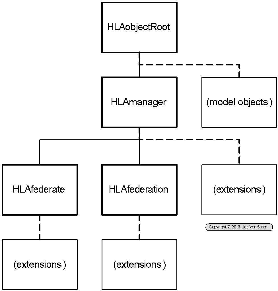
Figure 7 MOM Object Class Structure in Context
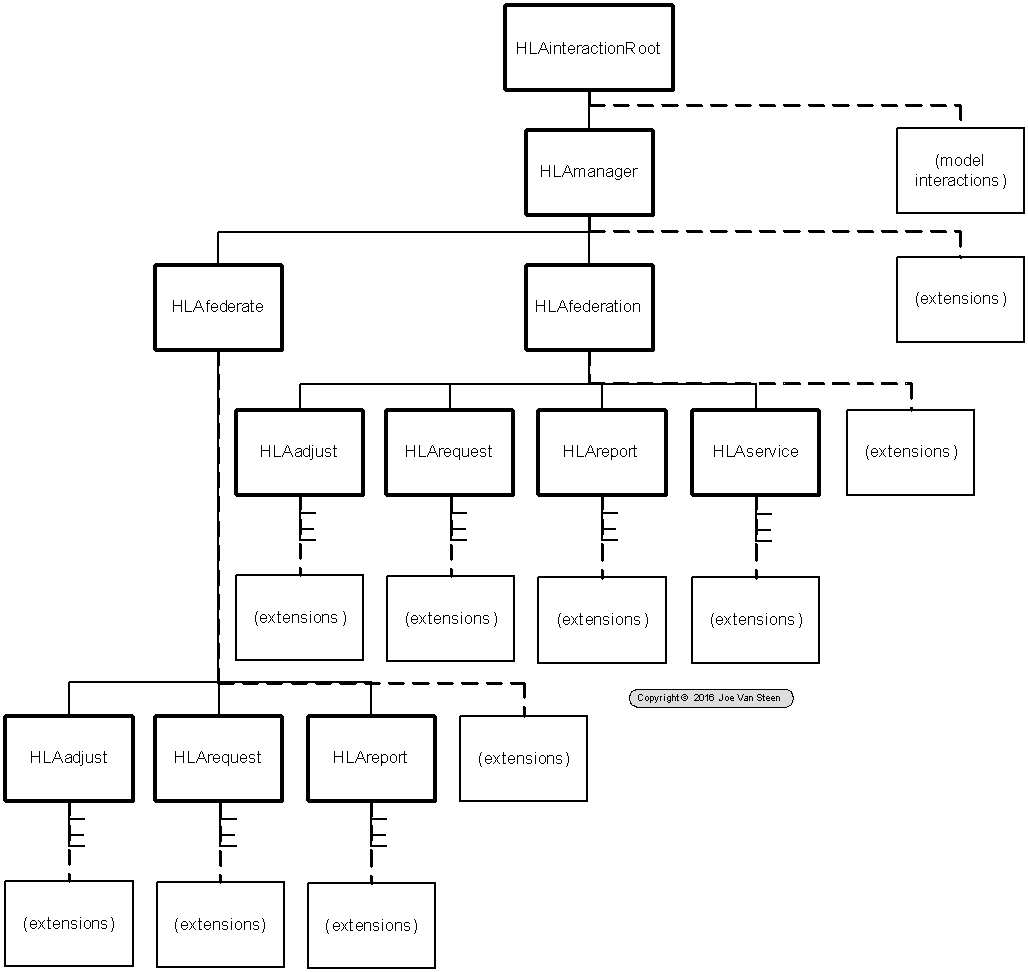
Figure 8 MOM Interaction Class Structure in Context
EATS Module Strategy
Client operates as a front-end visualization mechanism for the simulation. The actual simulation runs in the background processing tier, potentially on another machine. Communications between the client front-end and the simulation is via asynchronous messaging as shown in Figure 9.
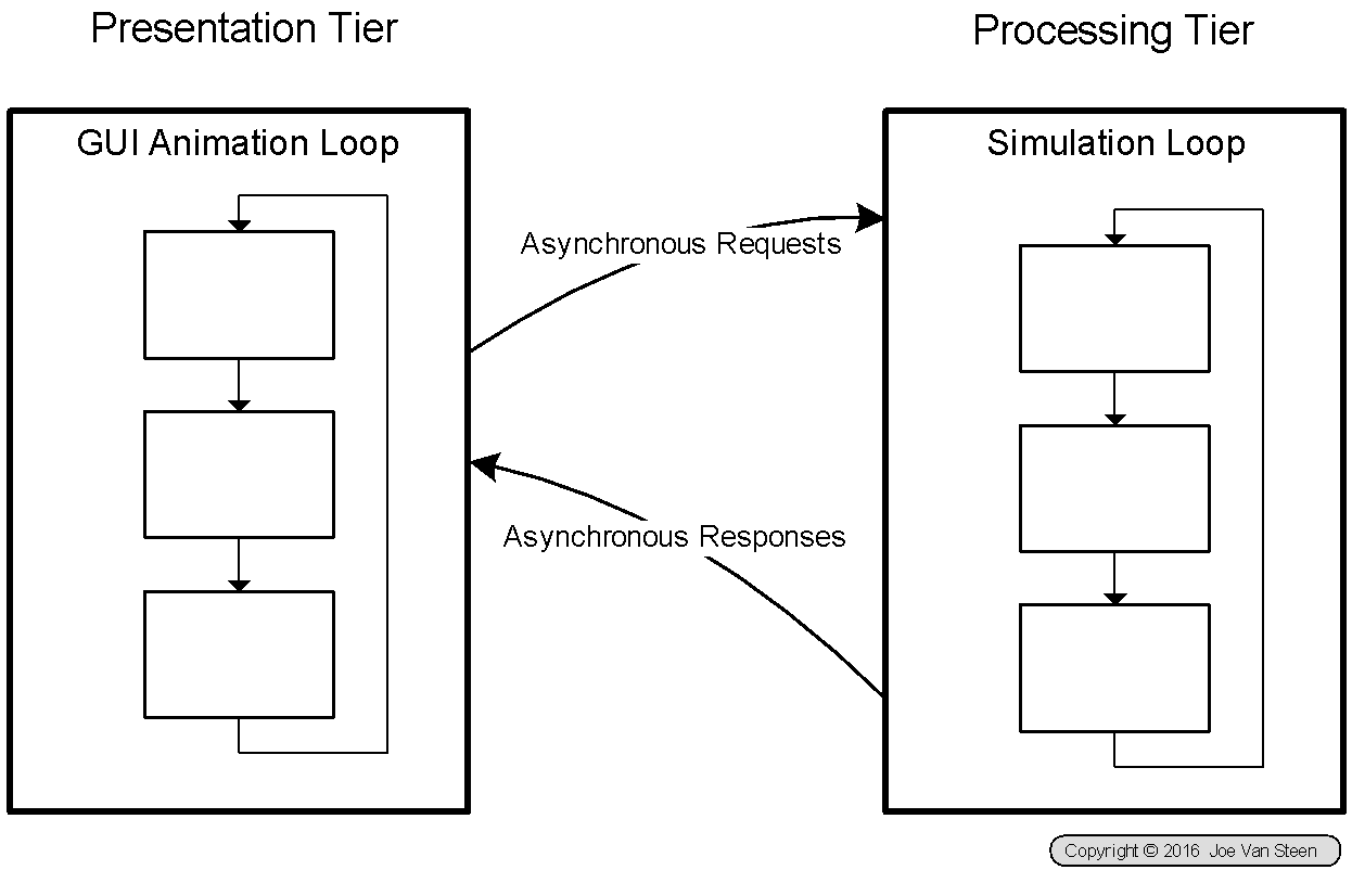
Figure 9 Simulation Client-Server Structure
Clients operate on their own thread, with their own visual animation loop. The simulation runs in its own processing space with an independent simulation loop. Multiple clients may participate in, or observe, the same simulation.
Packaging
In general, we have the potential need for 6 projects for each simulation. These take the following form:
Client | Shared | Services | |
Generalized Base | GC | GSh | GS |
Application Function | AC | ASh | AS |
Each is created as a Plug-in Project:
- GC - net.architectedfutures.eats.simulation.client
- GSh - net.architectedfutures.eats.simulator.core
- GS - net.architectedfutures.eats.simulator
- AC - net.architectedfutures.eats.sim.applName.client
- net.architectedfutures.eats.sim.sushi.client (Sushi Restaurant)
- net.architectedfutures.eats.sim.world.client (Hello World Sample)
- net.architectedfutures.eats.sim.fight.client (Food Fight Sample)
- ASh
- AS - net.architectedfutures.eats.sim.applName.services
- net.architectedfutures.eats.sim.sushi. services (Sushi Restaurant)
- net.architectedfutures.eats.sim.world. services (Hello World Sample)
- net.architectedfutures.eats.sim.fight. services (Food Fight Sample)
These are configured into 2 feature sets for application configuration:
- Application Client Feature = GC + GSh + AC + ASh
- Application Service Feature = GS + GSh + AS + ASh
Base Structure
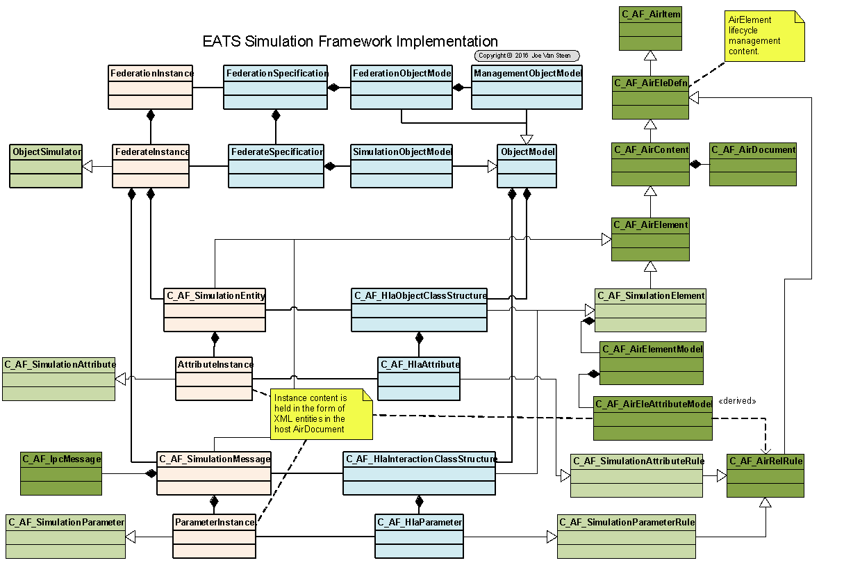
Figure 10 EATS Simulator Core Infrastructure
Client Structure
The current client perspective framework for the demo facilities appears in Figure 11. This replaces the Element Catalog of the AIR Editor Perspective as a navigator panel with the hierarchical set of parts displayed on the left part of the screen. This is similar to the "Class Hierarchy" used by the AIR Editor Perspective, but it does not lay out a set of elements from the dictionary. Instead the navigator shows a set of "parts" which conform to an Eclipse Extension family. For simulation models these would be "parts" which can be generated on the right hand side which can provide different views of a simulation.
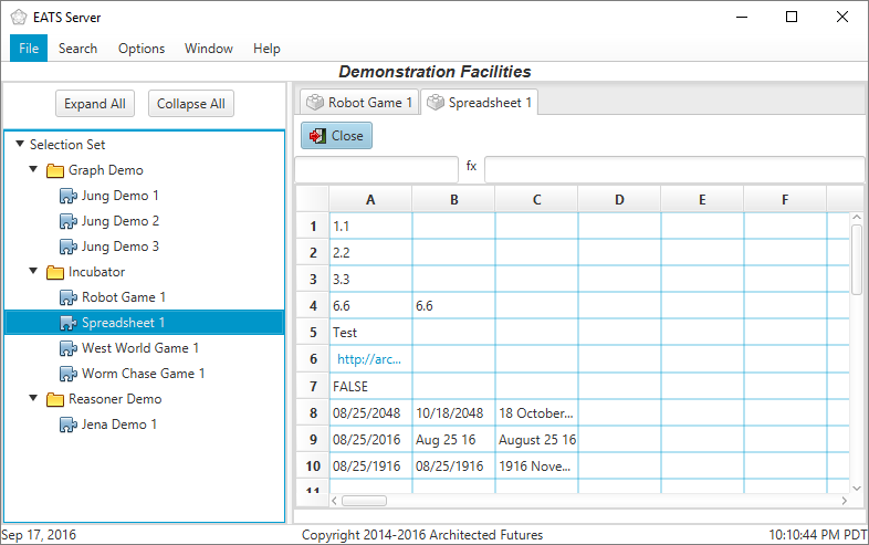
Figure 11 Current Demo Perspective
The user scenario for the modeling facility Client Wizard, a routine "open perspective" wizard extension, is as follows:
- User initiates use of the modeling facility from the New Tool Perspective dialog, as shown in Figure 13. These "open perspective" selections are implemented by wizards which open dialogs to configure the perspective to be prepared. The selections available on this first dialog (the one which may, or may not, include the option to use the modeling facility) are determined by review of the EATS toolsPerspective extensions available at the client workstation, as shown in the left hand element of Figure 12.
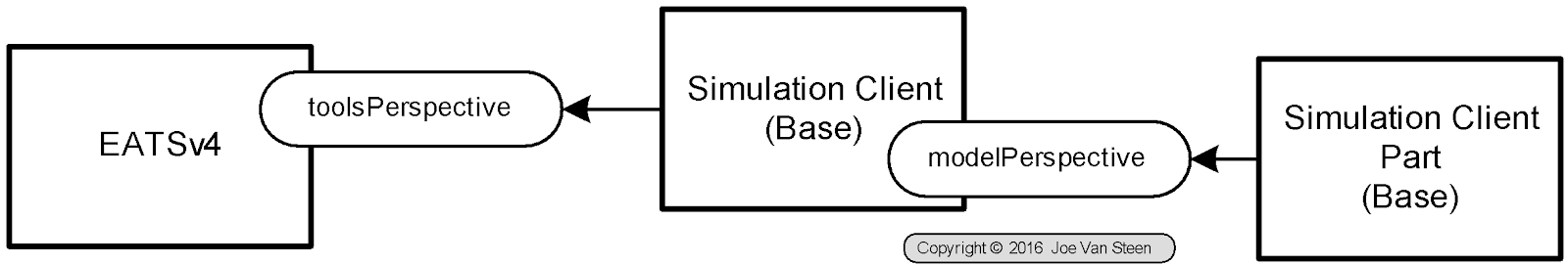
Figure 12 Simulation Client Extension Structure
- On activation the basic modeling facility wizard {W} offers a choice for the sourcing if the model to be used. Options include the AIR repository, a file import, running models[6], etc.
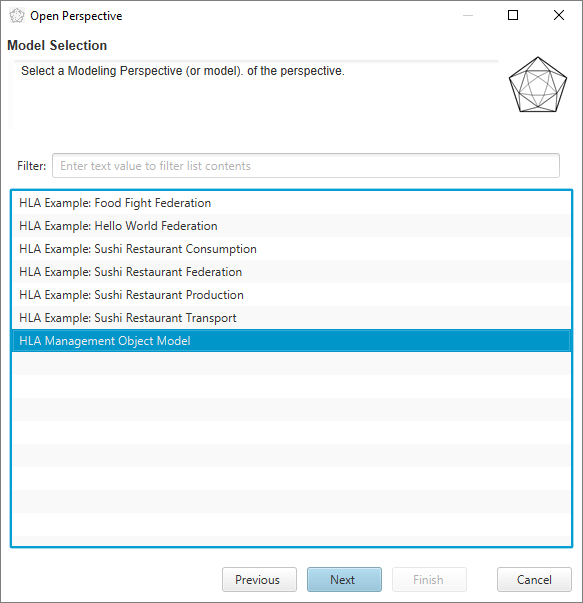
- Assuming the choice for sourcing was the AIR Repository, the wizard makes an query to the AIR repository for models. Hypothetically, the wizard should find one or more FOM/SOM elements, the "model" for the client federate to be configured, in the repository. These define the selection set of the available models as presented in Figure 14. The AIR Repository SOM/FOM model elements also provide GUID data to be used in filtering extensions in steps 3 and 4. The user makes a model selection and presses Next.
- User is presented with a choice of model explorer/navigator options as shown in Figure 15. The selections available on this dialog are determined by review of the EATS modelPerspective extensions available at the client workstation, as shown in the right hand element of Figure 12. This is the primary element that will implement the left hand portion of the running perspective. Select one, and press Next.
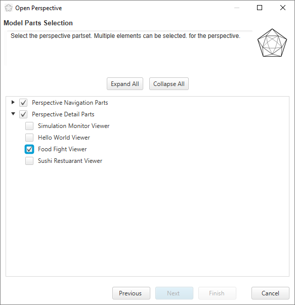
- User is then presented with the Model Parts dialog, as shown in Figure 16.This is a set of options regarding UI parts to be configured for the perspective. These may include viewers, editors, monitors, etc. depending on the user capabilities and the model being exercised. The selections available on this dialog are also determined by review of the EATS modelPerspective extensions available at the client workstation, as shown in the right hand element of Figure 12. Choose any combination of items and press Finish.
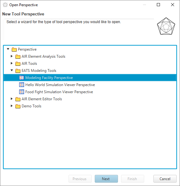
Figure 13 Modeling Option Selection
Model selection wizard page needs options to get model from file or running model.
Figure 14 Model Selection
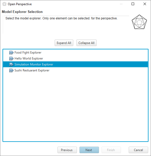
Figure 15 Model Explorer Selection
Should include choice from Fig 11 on page
Figure 16 Model Parts Selection
On completion of the user dialog, the wizard is then responsible for configuration of the perspective which implements the Simulation Client {C} framework. Simulation perspectives follow the same general form as most EATS dynamic collection perspectives. The framework is constructed from common parts and specialized parts which implement the modelPerspective extension for the chosen model type. These include cooperating C_AF_SimulationController, C_AF_SimulationExplorer (from step 3 above), and C_AF_SimulationVisualization and C_AF_SimulationTools (from step 4 above) as shown in Figure 17.
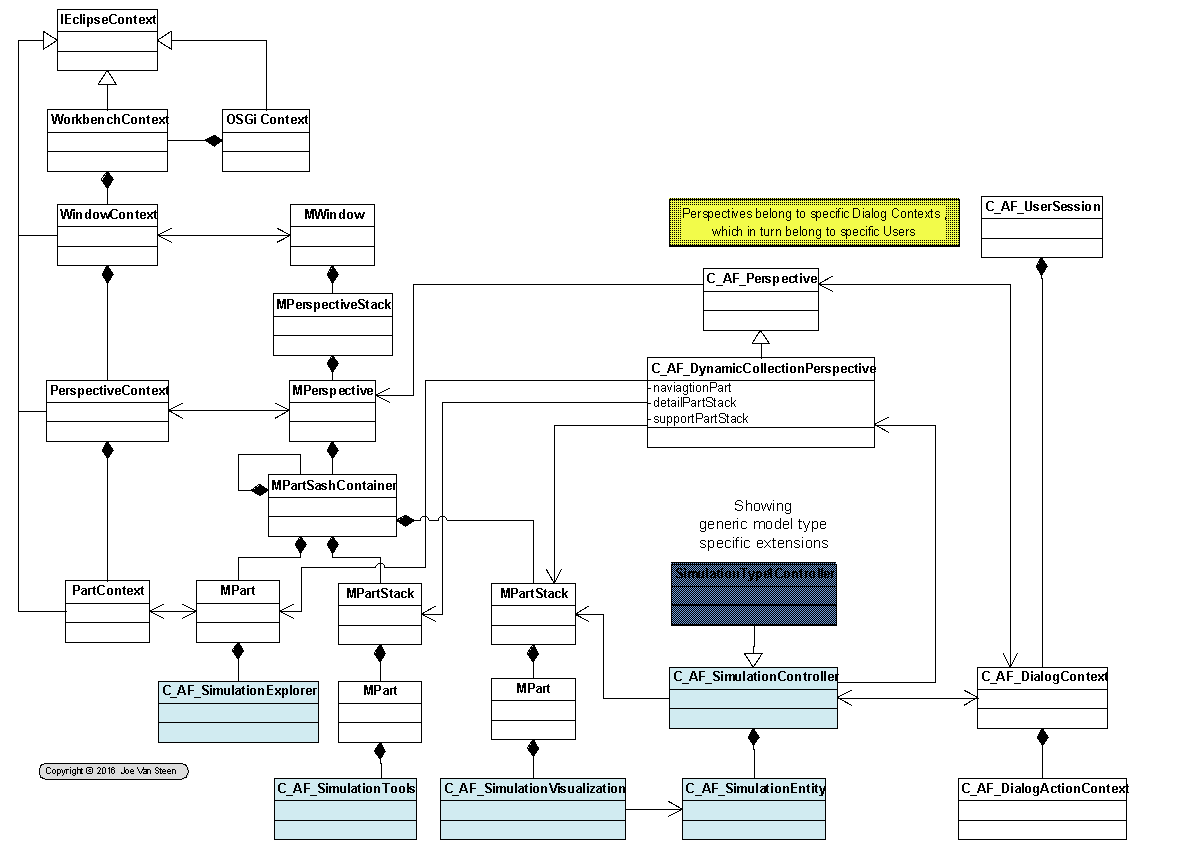
Figure 17 Simulation Client Structure
The general "pattern" for the perspective follows the model of the Demo loaded program set, but the perspective model space wants to also feature an element collection, similar to the regular editor.
- Parameter passing between the wizard and the loaded perspective happens via the DialogContext variable pool. The wizard preloads selected variables in the variable pool, and these are retrieved by the perspective, or its parts, by "known variable name."
- pointer to "perspective controller" (contains a pointer to the perspective)
- pointer to: "selectedModel" an C_AF_AirItem
- pointer to the plugin extension set for the navigator: Class Name: C_AF_RuntimeExtensionCollection
- pointer to: "selectedNavigator" an C_AF_SimClientExtensionElement
- pointer to: "selectedPartSet" an private ArrayList<C_AF_RuntimeExtensionElement>
- pointer to: "pluginExtensionSeries" a String with the plugin extension series name
- The SOM model loads in the place of the element collection. However, we still load an element collection, but one based on the SOM specifications.
- The explorer/navigation panel loads all client parts appropriate for the model based on the SOM and offers a set of "views" that can be used on the model:
- Model Editor
- Simulation Infrastructure Monitor Viewer
- Simulation Viewer (e.g., sushi screens), or interaction interface (e.g., worm game)
- etc.
- When initialized, the detail panel is empty. A focal model has been identified, but no view has been identified. Views are open for selection from the explorer.
- User is then free to select any of the tools for viewing or editing the model.
- Selecting views, is like selecting elements to edit; or in the demo, selecting a demo program to run. The "view" (element/demo) opens in a tabbed detail window pane.
- Multiple views can be opened for the same model. Each view becomes a tab.
The current editor window is shown in Figure 18. The scheme for visual interface of a multi-level element is to nest the editor window tab structure on a recursive basis. Comparing Figure 18 with Figure 11, the editor window in Figure 18 creates a new set of tabs below the Open/Close buttons for views of different aspects of the element model within the main part tab which shows at the top of the detail part window just below the perspective name in both figures. Elements with a single layer model should continue to have this appearance. However, elements with a multiple layer model, like SOMs and FOMs, would "nest" the tab structure as a set of layers.
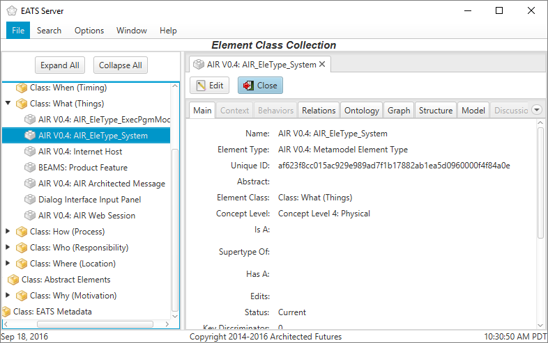
Figure 18 Element Editor Window
Starting at a top layer of an editor window, shown here as the "Main" tab, this window would show all elementary properties which appear at that level as the detail of the window, shown here as the window content. In addition, the top of the window would show a new set of tabs which define the structures that occur at this level defining the next level of structured decomposition. For example, when editing the model identification section of an OMT model the window shown in Figure 19 would appear as a sub-panel of the "Main" tab shown in Figure 18.
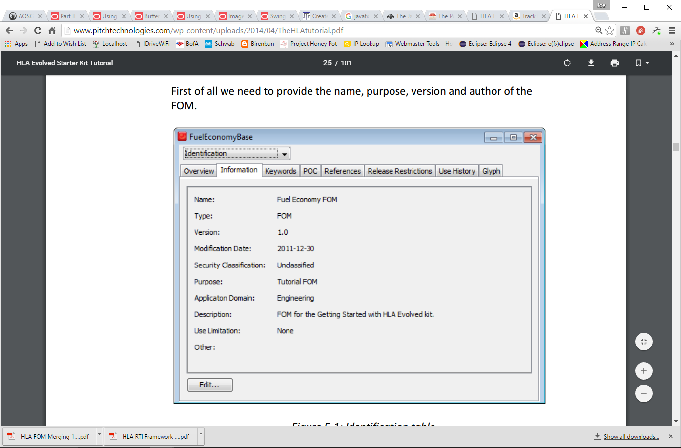
Figure 19 Pitch OMT Editor View
Extensions
Extensions for client UI work different[7] than extensions for background processes or services. Client UI extensions require:
- An Eclipse plugin extension, to provide the optional plugin mechanism. linked to ...
- An e4 application model fragment providing a partDescriptor for the UI part.
For service routines, the plugin extension identifies the class in the plugin which implements the plugin capability.
For UI the plugin provides the notification that the feature is available, however the UI code can not simply be loaded and executed. Rather, since we use the e4 application model to drive the UI, any optional UI needs to be integrated with the e4 application model. Thus the packaging for the plugin must also include an e4 application model fragment. UI parts provided via plugin extension services must identify a UI partDescriptor in the plugin extension. The partDescriptor, if the part is provided as part of the extension customization, must be provided in an e4 application model fragment as part of the plugin. The partDescriptor then provides the name and location of the implementation class.
Server Structure
Challenge
- How can a Federate Service Provider, in an arbitrary node, locate and communicate with another Federate Service Provider that is downstream (communications-wise) from a common base point.
- Given three nodes: A, B and C; A may be connected to B and C, but B and C may not be connected to each other. If A instantiates ServiceProviderB and ServiceProviderC, how can ServiceProviderB send messages to ServiceProviderC?
- Normal EATS messaging does not support this!
Resolution
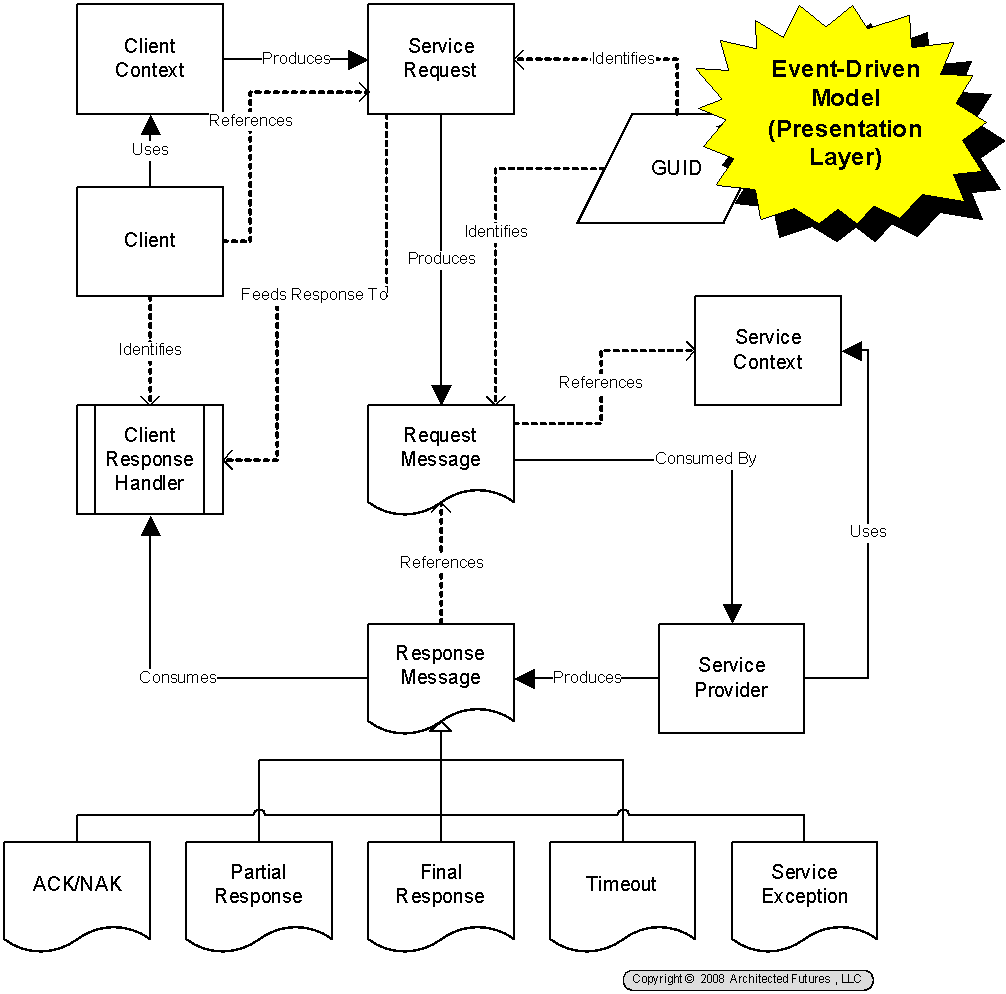
Figure 20 Presentation Tier Message Architecture

Figure 21 Cascaded Service Message Architecture
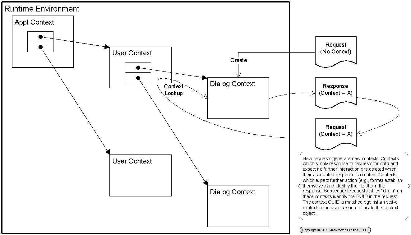
Figure 22 Presentation Tier Message Contexts
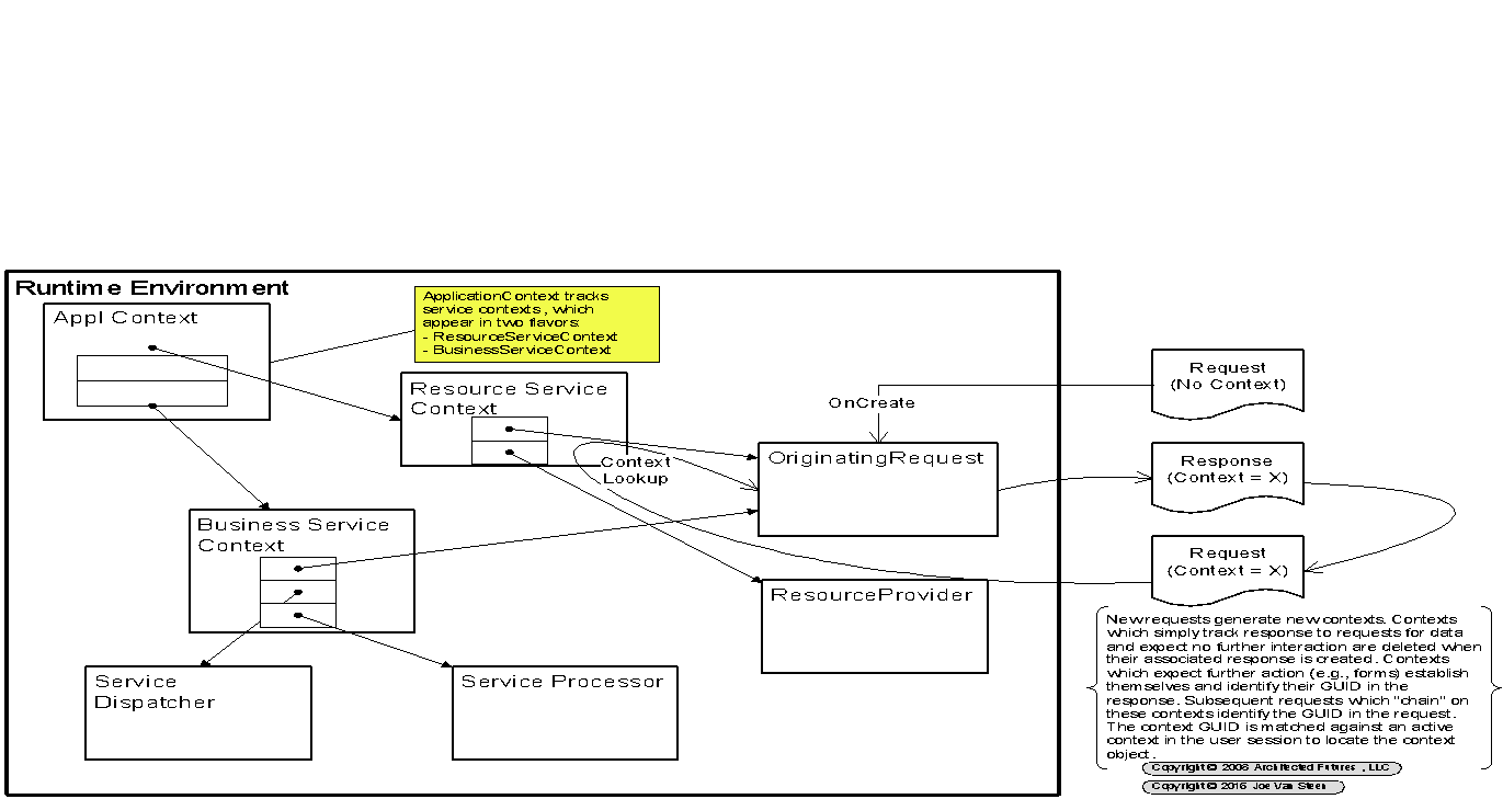
Figure 23 Processing Tier Message Contexts
Common Core
libRTI provides the interface between HLA processing and whatever simulation or processing happens in the federates. This includes translation and communication of concepts as expressed in the various simulations into HLA concepts of objects, attributes, interactions and parameters; and back to individual simulation concepts. libRTI includes the features of the RTI Ambassador to enable the federate to make service requests on the RTI, and the abstract form of the Federate Ambassador to open a bridge whereby the RTI can make callback requests on the federate. In addition to handling RTI service calls, the RTI Ambassador also provides a set of factory services that are used to provide factories for data management structures used in the communication of references to objects, attributes, interactions and parameters and their characteristics. The factories in turn provide forms of object handles and data management structures to enable communication between all participants in a federation during the operation of the simulation. The conceptual semantics for these elements are defined by the HLA specification, however implementation is vendor specific.
Vendor Specific Factories Provided
The following list identifies the vendor specific factories. EATS is required to implement these mechanisms as the provider of the EATS HLA RTI.
- AttributeHandleFactory
- AttributeHandle
- AttributeHandleSetFactory
- AttributeHandleSet
- AttributeHandleValueMapFactory
- AttributeHandleValueMap
- AttributeSetRegionSetPairListFactory
- AttributeSetRegionSetPairList
- DimensionHandleFactory
- DimensionHandle
- DimensionHandleSetFactory
- DimensionHandleSet
- FederateHandleFactory
- FederateHandle
- FederateHandleSetFactory
- FederateHandleSet
- InteractionClassHandleFactory
- InteractionClassHandle
- LogicalTimeFactory
- LogicalTime
- LogicalTimeInterval
- ObjectClassHandleFactory
- ObjectClassHandle
- ObjectInstanceHandleFactory
- ObjectInstanceHandle
- ParameterHandleFactory
- ParameterHandle
- ParameterHandleValueMapFactory
- ParameterHandleValueMap
- RegionHandleSetFactory
- RegionHandleSet
- TransportationTypeHandleFactory
- TransportationTypeHandle
Handles
Handles provide unique, internal identifiers to simulation elements. Users deal with them as abstract identifiers. The internal RTI processes use them to uniquely identify elements used in the simulation.
- FederateHandle
- ObjectClassHandle
- ObjectInstanceHandle
- AttributeHandle
- InteractionClassHandle
- ParameterHandle
- DimensionHandle
- TransportationTypeHandle
- RegionHandle
- MessageRetractionHandle
Message Strategy
Simulator messages use a nested message scheme where the semantics of the simulation message may be reversed from the semantics of the EATS carrier message.
All non-infrastructure, simulation message traffic is conducted in the context of EATS conversational messages. This means that EATS routing is conducted via the conversation ID of the message to find the message target in one direction, and the designated "response processor" to find the target in the other direction. The normal routing parameter data MsgObject, MsgAction, MsgVersion and MsgMode are ignored (by the EATS infrastructure). Response codes on response messages, however, are inspected and acted on.
To avoid confusion, simulation messages will take the form of a specialized extension of I_AF_TransferObject, which occurs as the content portion of both requests and replies. This new extension, C_AF_SimulationMessage, repeats selected IPC infrastructure data to define the semantics and targeting of the simulation message. These semantics may be in agreement with, or contradictory to, the semantics of the host EATS message. It is the responsibility of the ambassador modules to ensure correct correlations.
A participant in a simulation wishing to send a message will use a Send interface on the ambassador to communicate the message, regardless whether that message is ultimately communicated via an EATS request or response type carrier message. Similar to today's EATS architecture, responses will be provided via message-driven events for the recipient, regardless if they were carried as new requests or responses. This is similar to the current logic in service processors.
Simulation Messages
- Still need a scheme to handle multithread issues around communications. Need multiple msg queues to be able to force processing of all current messages, but be able to defer messages for future clock cycles.
Set-up Scenario
- Simulation Facility {RTI}, a Resource, or a Service Provider
- Major components (from RTI_NG13 Programmer Guide) as shown in Figure 24.
Figure 24 RTI Components
- RtiExec process manages the creation and destruction of federation executions. Each executing federation is characterized by a single, global FedExec. The RtiExec may manage multiple federation executions with different names within the same network.
- FedExec manages multiple federates joining and resigning the federation execution (the simulation process).
- libRTI is the RTI library which extends RTI services to federate developers. It is the portion of RTI code which is implemented within the federate process. As shown in Figure 25 it consists of:
- The RTI Ambassador which supports a call interface implementing all HLA service calls defined for federates to make on the RTI,
- The FederateAmbassador interface defining all callback methods to be implemented by the federate, and
- vendor specific implementations of various HLA defined object types and factories for their production in, or by, the federate.
Figure 25 libRTI Integration with Federate
- The RtiExec, the FedExec and the various libRTI instances communicate via their own internal IPC protocols, as shown in Figure 24. The hybrid nature of this "wire protocol" is the reason unique vendor specific libRTI modules are required to interface with a federation managed by a specific vendor FedExec.
- Simulator {S}, a Service Provider (Federation)
- Correct this. Each Federate has its own Simulator Engine. The "simulator" is not centralized. Simulation coordination is centralized via simulation time management. Federates are simulators, with their own engines appropriate to their nature.
- Simulation Behavior Module (Federates) {F1}, {F2}, {F3} ... {Fn}, Service Providers
- Simulation Management Module (Federate) {M}, Service Provider
- Simulation Observer/Participant Module (Federate) {P}, Service Provider
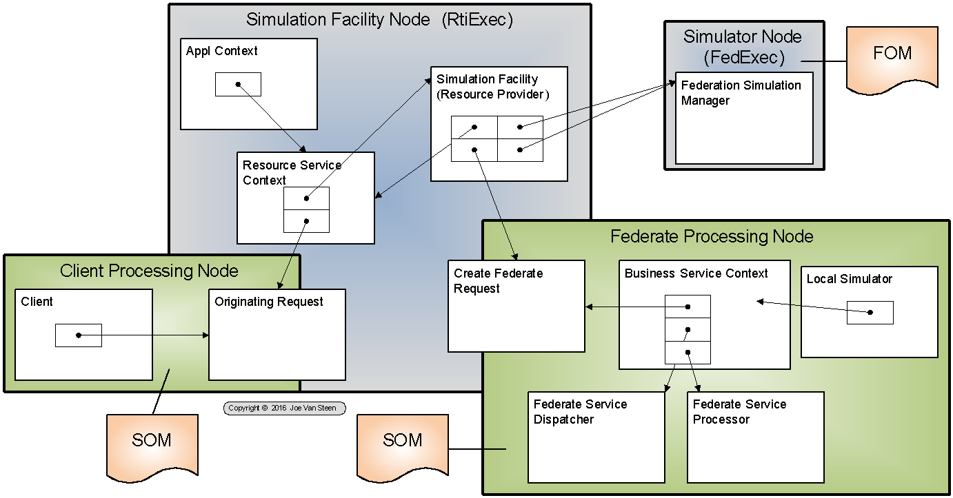
Figure 26 Simulator Framework
The visualization above needs to be updated to show the overall RTI configuration of Figure 24:
- RtiExec is big Simulation Facility Node
- FedExec is Simulator Node (Fed coordination, not actual driver; other than driver of sim time
- libRTI is different for client and service side federates
Needs to also be thought about in terms of hierarchical simulations. Is a single FedExec used to manage all levels of a combined sim, or does a new FedExec get spawned to handle each branchpoint. (see paper)
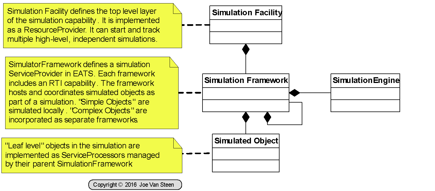
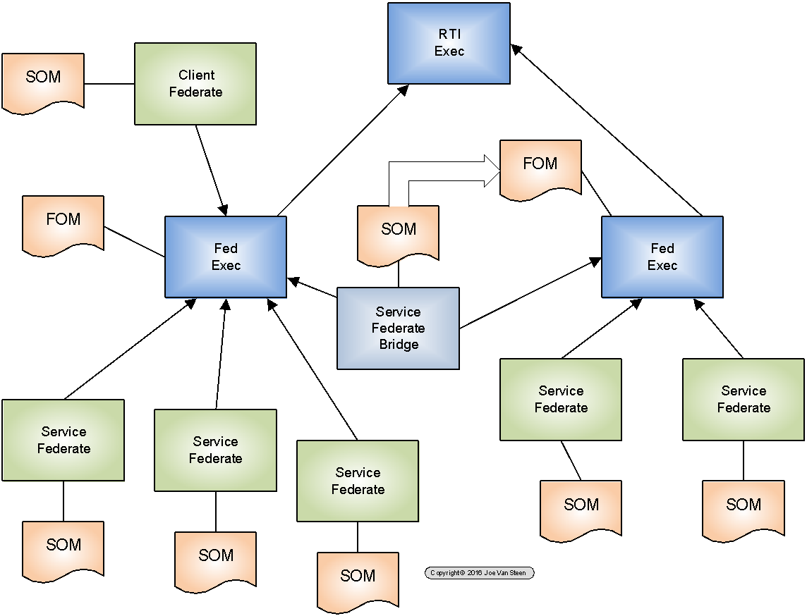
Figure 27 Cascaded Simulations
- Wizard {W} attempts to either create a simulation, or join an existing simulation as either a participant or observer.
- Wizard needs to access a broker or a catalog[8] that defines what simulation capabilities exist, and what simulations are executing, or established, in the accessible address space. This "catalog" exists as an accessible {RTI} Simulation Facility.
- Wizard {W} establishes long-lived conversation with Simulation Facility {RTI}.
- Wizard passes conversation with Facility {RTI} to Client {C} via the Dialog Context established for the perspective (See Figure 22). This allows Client {C} to "find" and converse with {RTI} via an established conversation ID.
- {C} can now query about running federations, and may join in a federation as a federate.
- At 1b[9] (or 1c), Facility {RTI} starts a Simulator {S} as a service module, whose "address" become Conversation {S1} (known as a link between {RTI} and {S}). Simulation {S} is now identified as {S1} in a table in {RTI}.
- Any conversation with {RTI} can find {S1}. Since {RTI} is a resource, this can be an internal table. ({RTI} cannot be a service, because a second client could not address the same context. See Figure 26, each client connection with {RTI} will use a unique Resource Service Context. But each client connection with the same ResourceProvider[10] can access the content of that ResourceProvider, and thus query to locate {S1}.) This would also work with a database catalog entry.
- {S1} becomes a shared, known GUID reference and {RTI} fills the role of a switchboard. Conversations with {S1} (from {W} or {C}) need to be routed through {RTI}, and {RTI} will re-route over the known, open conversation ID.
- Since {S1} was established by {RTI} all message traffic will flow with the following EATS syntax:
- {RTI} to {S} travels as Request
- {S} to {RTI} travels as Response
- Facility {RTI} needs to have a copy of the RID and FDD for the simulation. The RID is intrinsic to the {RTI} and can be sourced internally with possible adjustments based on the model types supported. The FDD consists of the FOM and MIM information required to create the federation. In EATS, this can be sourced from the specification for the element (system) being modeled in the form of the combined Element, {E}, and Element Type Model, {T}, documents.
- {T} defines the structure of the system, including composing sub-element types with cardinality and ordinality specifications, and relationships with other "exogenous" elements (the environment). {E} should define the element instances that implement the items defined in the element model. The simulation model instance is a new AIR Element, {SD}, of type simulation instance, which tracks to the model defined by {T}l and with a specific "model of" component attribute which points to {E}. To the extent the simulation is documented in {SD}, multiple simulations can be conducted and the results in {SD1}, {SD2}, {SD3}, ... {SDn} can be compared.
- Using the data in {T} and {E}, the Object Table portion of the FOM can be created defining the "objects" of the simulation. For each object in the table (an AIR Element Type) a Service Processor can then be identified and one or more federates ({F1}, {F2}, {F3}, ... {Fn}) can be created as Service modules. Each Federate will be associated with its own BusinessServiceContext, obtain a unique ID as a key in the simulation table, and be associated with {S1} as its simulator.
- On instantiation, the federate can:
- Review its own Element Type Model and configure its SOM.
- Join Federation {S1}
- This traffic is routed through {RTI} using reverse messaging over the established conversation path:
- Messages to {RTI} for routing to {S1} need to be sent as "partial replies" on the open conversation. These can then be send "forward" as messages to {S1} from {RTI} on the open conversation channel.
- Replies from {S1} to {Fx} via {RTI} are send as a reply from {S1} to {RTI}, then a message from {RTI} to {Fx}.
- Additional support message traffic by the federate to other aspects of EATS are generated and handled as normal EATS traffic.
- Using traffic patterns in 3b, the federation becomes initialized as per the FDD.
- {RTI} notifies {W} that the federation has been initialized.
- {W} instantiates {C}
- {C} converses with {RTI} to join the federation as either type (participate) or type (observer).
- Client can ask {RTI} for a list of other federates and can establish conversations with any of them to obtain statistics, etc. This includes MOM, or any federate object.[11]
- No need for client to monitor and buffer statistics. Statistics for graphs, etc. can come straight from federate by subscription, or as report at end of execution.
- If {C} is the owner of the simulation, it can start, pause, resume or stop.
Benefits
- Allows all federates to operate as independent modules, independent from need for separate management in either {RTI} or {S}. The infrastructure keeps a series of separate instances of each module type.
- Module type is identified by object type GUID signifying what type of behavior is able to be implemented. These are identified ahead of time via routing tables.
- Federate instances are unique for each instantiation and identified via conversation ID of the "create" instance for the module GUID type. Context is maintained by EATS standard infrastructure.
Challenge
- Create a reverse message flow handler capability in {RTI}
Ambassadors
Ambassadors are adapters that provide a convenience facade between federates and the RTI to support a two-way communication service. In HLA semantics there are two ambassadors:
- RTI Ambassador - provides abstraction mechanism for the federate to invoke an RTI service. The RTI is expected to be remote, but the service call is conceived as operating as a synchronous, remote procedure call. Call is via a standard API method (defined in the interface RTIambassador.java) with a potential result returned. The service call may also throw an exception.
- Federate Ambassador - provides abstraction mechanism for the RTI to invoke a "callback" on a federate. Callback is via one of a series of standard methods (defined in the interface FederateAmbassador.java). All callbacks return void but may throw a FederateInternalError exception to indicate a processing error. Callbacks can be turned on and off via specific service calls on the RTI Ambassador. (New service calls are not allowed during a callback.[12])
In EATS the ambassadors also obscure the underlying EATS message syntax and present conversations in the mode of the logical semantics. We use two flavors of each of the two ambassador types defined in the HLA. The difference is based on whether the federate is "upstream" or "downstream" from the RTI. If the federate is an EATS Client to the RTI, it operates "upstream" and technically views the RTI in the manner specified in the HLA specification. If the federate is an EATS Service to the RTI, it operates "downstream" and technically views the RTI in a reversed manner.
RTI Ambassador {Federate -> RTI) | Federate Ambassador (RTI -> Federate) | |
Federate is EATS Client | A1 | A2 |
Federate is EATS Service | A3 | A4 |
Client RTI Ambassadors (A1)
Used by client modules, or client-side federates, to communicate HLA messages to the RTI. Operates in a "normal manner" according to HLA documentation as a synchronous method call. Service calls obscure asynchronous message calls to the RTI. Callbacks may occur while service call processing is in effect. Completion of the appropriate RTI response message closes the synchronous service method call with a return result or an exception.
- This is a method call to one of the services defined in RTIambassador.
- RTIambassador encodes an RTI service call message
- If msg is connect, call IPC connectionSend, else call IPC continuationSend
- IPC communication is separate module. Maintains a single conversational service with the RTI[13].
- connectionSend is used to open an RTI connection. Rejected is already open.
- continuationSend is used to send a service request, or callback response. Rejected if no connection exists.
- IPC communication handles incoming "responses."
- "Final" response closes the connection.
- Partial response to original request is either
- Connection acknowledgement
- Callback service
- Responses to service calls are identified as responses to specific service calls identified by GUID.
- Responses to services calls (5c) are routed to RTIambassador by callback, keyed to request.
- Callback service requests are routed to FederateAmbassador for processing.
- FederateAmbassador callback return messages are sent via continuationSend process.
Client Federate Ambassadors (A2)
Used by the RTI to communicate HLA messages to client-side federates. Operates in a "normal manner" according to HLA documentation as a synchronous method call which may occur during A1 method call suspension. No result data is returned, but failure may be indicated via a thrown exception. Exception result will be reported to the RTI by the ambassador.
Service RTI Ambassadors (A3)
Used by Service Processor federates, and the Simulator, to communicate HLA messages to the RTI.
Service Federate Ambassadors (A4)
Used by the RTI to communicate HLA messages to Service Processor federates, or the simulator.
Automatic Logic
Automatic logic can come from:
- Standard module for a type, eg Wentworth store (stop when full/empty)
- General purpose logic specified as an equation which is resolved via eval4j
However, these still require some feature that can implement the "automatic" logic, such as a module which can be applied to "any" element (in the case of 2), or a module which applies to a type of element (in the case of 1)
References
From: http://www.hartech.co.il/tech_simulations.html
Notes
Behavior Modeling
From http://www.hartech.co.il/tech_modeling.html
Through the development of the CGF we have developed unique technologies through which we provide CGF as well as other Autonomous Platforms the ability to behave in accordance with user defined behavior techniques and reaction paradigms.
One and the main advantages of the SSG Simulation Engine is the large number of autonomous Computer Generated Forces (CGF) managed in the distributed scenario. The behavioral models are the main added value of the CGF Package. This module provide the CGF with the "intelligence" behavior which is in accordance with the domain expert definitions. Our technological approach is based in a combination of a State-Machine together with some concepts of SOAR. The behavior modeling paradigm is defined as a multi-phase action which is based on:
- User Friendly Behavior Editor - this application enables the User (Domain Expert) to define the required behavior and reaction paradigm.
- Run time decision making algorithm which implements the required behavior as a function of the perceived situation.
The Behavior Editor is a user friendly GUI application which enables the Domain expert to define the behavior of the entity using the drawing of a State-Machine.
The behavioral modeling of the CGF is based on a multi-layer modular decision making paradigm which includes:
- Situation Perception - This module is responsible for generating the perception of the entity based on the received information (simulated or real sensors).
- Decision Making - The decision making is done by our "Decide" module, this modules exercise the techniques defined by the Domain expert based on the perceived situation. The decision module is a combination of a State-Machine and SOAR.
- Logical Interpretation of Decision to Physical Actions - the logical instructions generated by the Decide module are interpreted to physical actions which are to be exercises by the platform. Each domain of actions is interpreted by a different controller ensuring translation of the logical action decided to a physical action that can be executed by the platform.
- Implementation of the Physical Actions - The Physical actions are implemented by a dedicated module which is responsible for the physical management of the platform. This can be a Simulation Module or an actual controller such as an Automatic Pilot System.
The behavioral model implemented is constructed of several models which operate asynchronously but in concert in order to produce a logical behavior of the CGF.
The main advantages in this multi-layer architecture are:
- Modularity - enabling high level of reuse of the code in different applications
- Close linkage between the Domain Experts knowledge and the end system behavior
- Application independent
General
What we are doing with the current code is recognized as Patterns-Based Software Engineering. Our Lee Ackerman PBE book has algorithms and stuff related to this topic.
- Pattern Instance Notation can help with the macro view of how to map AIR Elements to model elements - i.e., how to map patterns sets to implementations of that pattern.
The whole concept of simulation is a version of Behavior Model. "A use case captures a contract between the stakeholders of a system about its behavior.[14]" A Behavior Model is a use case experiment.
- We can have multiple use case scenarios associated with a system.
- Each use case expresses one or more actor/stakeholder perspectives.
- With the simulator we are running one or more simultaneous use case experiments against a given design to determine how it measures up to stakeholder requirements.
- This could be done today, and is done, by transcribing designs between tools. Scripting parts of a design into a simulator for selected requirement evaluation. The cools thing about what we are doing is we simulate from the design spec. And, we can simulate everything in the design to help reduce hidden surprises. Including a full simulation of the whole.
- Simulation behavior model is based on (See FBS+Q pg 36):
- Flow model
- Material flow,
- Information flow,
- Control flow, ...
- State Model
- Both
FBS+Q
- EATS 82[15]:
- Behavior, function, structure + Quality.
- Quality goes across a series of factors (cost, (structural) performance, appearance, satisfaction, ...) each of which have accuracy and precision measures.
- Six Sigma provides tools here.
- This provides the basis for architectural evaluation and scoring, and failure management.
- EATS 79:
- If EATS locates element behavior for modeling by looking for a hierarchy of extensions advertising Element GUID object behaviors, we can accomplish distributed inclusion by putting different detail or generic behavior on different nodes.
- EATS should climb the element hierarchy to find behavior modules. If detail type behavior is not available, then climb the class structure, and use general behavior.
- If detail is found ... , (it may be a complete submodel).
- For this to work well, we might need to be able to remotely activate and deactivate the availability of the remote behavior modules.
- Another option is to have the hierarchy appear as part of the FOM, then flip switches to decide what components and level of detail should be modeled.
Model Taxonomy
Go to the question of: is there a valid taxonomy (similar to Zachmann categories?), that describes guaranteed inclusion for model characteristics, or model types to cover our problem universe?
See http://www.engr.usask.ca/classes/ME/886/Handout%202010/FBS%20paper%20June%202005.pdf
- Structure emerges to have State
- State emerges to have Behavior
- Behavior emerges to have Function
Function relates to Purpose. Purpose come from Role, which is a matter of perspective.
- If a Purposeful System is functioning correctly, the exhibited function will be in agreement with its Purpose. If it is contravening to the Purpose, it can be said to be dysfunctional.
- For a non-purposeful system (POSIWID[16]), function is outcome or exhibited behavior; typically in a form that can be depended on. Purpose come from how the system is used, or the influence it has on either its subsystems or its environment. If a POSIWID system, e.g., a steel beam, is functioning correctly it is in agreement with the use (purpose) placed on it by all of its stakeholders from their individual perspectives. If it is contravening to one or more stakeholder's utilizations, it can be said to be dysfunctional.
Ongoing Design
- EATS 81:
- Next level of development is figuring out how to abstract and layer system models. Base will be generic version of models from the system zoo. Then an "application" model wants to use the generic model as a macro to generate a specific case.
- Two directions:
- 1st Element is an instance of a type, or class, which has a behavior model, and the element needs to be fitted to the model.
- 2nd Element is assigned behaviors defined by generic models, e.g., predator-prey.
- EATS 78 XML Parsing:
- XML parser for simulation model might serve as model for Xml parser for XMI models also, or I/O mechanism for output of EATS elements as XMI.
- Need to include generation and recognition of EATS guid as an element in OMT parsed model data.
- EATS 2016Sep21 External Items
- We need a way to map external items to internal elements and GUIDs.
- The internal item should have some sort of mapping to the real external item. If the item is in electronic form, we should be able to implement a way to obtain and read it.
- The external item should be uniquely identifiable. It should be able, in some manner, to know it's identity. (For example a file knowing it name and or location. A program knowing it's name and namespace.) For items which people reference, different people should be able to use some essentially guaranteed unique ID that is the same and recognizable by all users - A book ISDN(?).
- The internal item needs to know the external ID and should be able to create a look-up reference to itself. That reference can be used by processes which maintain the external item (such as software analyzers, etc.) to post updated information in the repository about the item.
- This provides a mechanism for automated maintenance of selected items.
- Namespace schema needs to be thought out
- This allows specification of web-page output, or code indexed to documentation.
ToDo
- 9/24/16
- When in the Dictionary element perspective which exposes the class hierarchy and element types, it would be useful to be able to right-click a type and then select an option to open a "type perspective" for that type.
- The class perspective stops the element exposition at the element type level. It does not expose the elements of that type. That's what the jump to the type perspective would do, to be able to continue the drill down (instead of having to go to the Open -> Perspective -> menu process.)
- EATS 80:
- 1. Interactions are instances of activity. They are actions associated with events. They are components of relationships, and act on objects.
- 2. I should try to begin to code/refactoring both client UI and background service pieces of example models, Restaurant, Hello World, Food Fight.
- This will start providing an implementation model to see how the new Rti pieces fit in. It will allow work from both sides, the same model and the consistent RTI.
- Different forms of client need to be Clint wizard extensions. Wizard makes RTI connection and post RTI AMBASSADOR to context.
- EATS 83 Object Scale
- For simulation work we need a, possibly nested, set of object descriptions and visualizations that vary based on zoom level scale.
- This relates to fine grain vs course grain models of spheres, and related items. Similar to ArcGis shifting details of maps at different scales.
AIR Repository Development
Metamodel Development
Metadata Management Notes 9/28/2016
- Property type specification in the construction of Element Models needs refinement. The original model had two elements:
- Property Definition (what is it?)
- Rule Specification (Who gets it?)
- We have brought these together so we can specify the rule and the property in one shot.
- Problem: We need multiple versions of the property if Cardinality and Ordinality are not consistent.
- This seems to be partly a function of how we apply properties to elements.
- We use an assignment technique where they are made available for a class of items, and then filled out for a specific item or type. This is a bottom up assignment scheme.
- Cardinality and Ordinality seem more of a top down thing, This element wants a required single instance, these others want optional lists.
- Once the assignments are made and an Element Model is constructed, the design scheme works. However, for the modeler/editor it is problematic.
- Might also help if we could clone, but duplication of specification across multiple "rules" is not good. Even if they are semi-static.
Simulation & Modeling Notes 9/5/2015
- We should have some high level conceptual entity definitions for model base types like entities and relationships, stocks and flows, etc. This is a two tier specification as shown below in Figure 28. Metamodel specification on the left is used to derive the detail "refined" elements on the right. This is true for the model as a whole, as well as the internal of each model.
- Both stores and flows are entities, not relationships. Stores connect to flows via relationships.
- These metadata types are conceptual only from the metamodel perspective. They are structural base elements which define consistent base elements from which a series of more specific element can be derived, as seen in each of the two representations in the figure.
- This allows one set of consistent modeling code to operate on entities as per the specification of the base element, and drive models defining any of the more refined system definitions (conceptual, logical or physical) as derived from the base element.
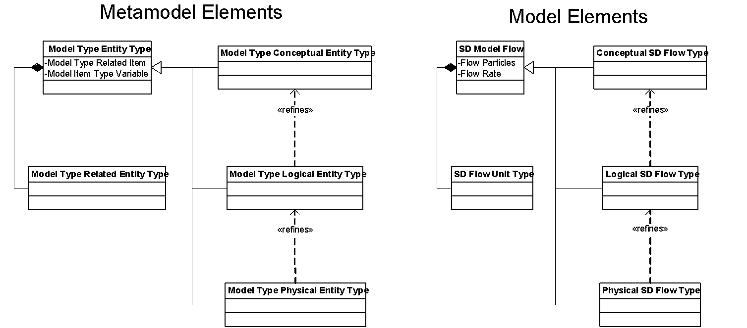
Figure 28 Modeling Framework
- We can also have default base elements and variables for selected specifications that are required as part of the model type. These can be conceptually "extended" in the users model, but the common modeling code does not care, since it operates on the abstract base definition. Polymorphic overrides can be used to tailor the model behavior.
- For example, generic SD model code can be programmed to determine if a flow is on or off, and if it is on, compute the number of "Flow Particles" that will move in a unit of time given a specified "Flow Rate." It can then remove that number of "SD Flow Unit Type" particles from a "Source Store" and add them to a "Sink Store."
- Models can be edited for consistency of units between flows and stores.
- Stores can have different logic applied based on unit types.
- For example, a form of Godley tables can be used to track entropy and balanced equations for money flows, or potentially to track conservation of energy. Another store type, which might be a factory, can perform transformations which convert entity types from one type (raw materials) to another (finished products).
- Metamodels as per the left of Figure 28 provide a consistent base for the modeling system within EATS. Then:
- Each general type of model derives a framework along the lines of the right side of Figure 28 which provides the basis for deriving models of that type at various levels in a coherent pattern.
- The AIR entity suite defined by the right side model then becomes the metadata entity types for a user to define one or more models of that type. If multi-layered models are defined, EATS assists in model management and audit according to the conceptual levels of the models. This also provides the basis for model aggregation and summarization.
9/24/16
- Need metamodel framework for simulation re mapping of EATS entities to HLA Object Model. This can be "hard coded" or it can be an example of pattern mapping.
- Need updates to metamodel to reflect conceptual breakout of properties.
- At the EATS Tool Suite level[17] for the basic AIR data management of AIR documents, we have our basic frame of element composition as properties, relationships (associations), or models.
- Everything in AIR is assigned an element type.
- To create an element type whose value set is a set of element types, first we need to create an element type for the enumeration, then we assign the enumeration as the element type of the enumerated value setting..
- At the next system level (Architectural Modeler), as we start to build tools that makes use of the data, we need to further characterize what kinds of things the properties, associations and models are.
- objects are things, elements
- states are conditions or situations of things
- they are measurements or evaluations
- they are abstract concepts
- they reflect and evaluation of the state of properties or relationships
- they tend to be fuzzy and referenced in terms of enumerations
- conditions are states, or state changes (thus properties)
- enumerations are lists of values which can be cataloged as a value set
- interactions are relationships
- transitions are interactions, from one state to another. The property that holds the state doesn't change, but the value of the property changes. The value specifies state.
- it might be useful to have separate statements about property as an item, state as an item, and then specify the relationship between the property and the condition: x implements (or carries value of) y.
- properties can be manipulated by simple data management, including utside of models.
- state conditions (the value of those properties) requires conceptual awareness and significance to be of value. It doesn't really come into meaning until viewed by a human, or viewed in a simulation process.
- Whether or not something represents a state, and the nature of that state
Documentation
People keep asking what Web 3.0 is. I think maybe when you've got an overlay of scalable vector graphics – everything rippling and folding and looking misty – on Web 2.0 and access to a semantic Web integrated across a huge space of data, you'll have access to an unbelievable data resource …
And, when you can animate it and incorporate it into models of actual and hypothetical systems ... you'll have EATS ("tools and strategies ... for boiling the ocean" and "A tool for making the connections that matter").
Preview Notes
The concept of using "self-documenting" element specifications only goes so far. We also need "Content." For that we need to develop the "Article" model and related material from our "Library" experiments in Thana's class. We also need to be able to read and store images. Then, there is a possibility we can import from both our Drupal site and from the old documentation in the Tiki-wiki archives, and all of the Word document notes assembled as a library.
Content
Part of the concept of EATS is model recursion through conceptual system levels. The EATS AIR data repository is the "system bus" for tool suite integration and interoperability. If we provide better documentation for the entries we make in the repository, and we create entries to define EATS logical design as entries in the AIR database, we can start using EATS as our actual reference model as a self-documenting system. This is the equivalent for "EATS JavaDoc" about the system. It is a physical realization, or realization foundation component, for the "fully eat and digest your own dog food[18]" capability that I've been trying for since the start of AF, and earlier.
- "Active Data-Dictionary" uses database look-ups to answer documentation questions.
- For use by "Help System" for online user documentation
- For use as a developer to understand the system internals
- Requires enhancement of thinking about how text is encoded. Potential need for ability to do mark-up, and/or html as we develop more documentation type items.
- If we do this according to known types, we can use the HTML editor that is vanilla within Java for edit, and use the browser control for viewing. That gets us going with HTML and plain text.
- Then we can expand to some other parsed forms, including code and XML, and ...
- Requires pseudo-duplication of our PHP web facility to generate standard "book front matter" on web books into print publication framework.
- Requires development of a "meta-model" for system documentation for development of categories for use to document design.
- "Yellow Book" + "4+1 Unified Process" + UML + WISDM + ? + our own methods and processes. Primarily this is target as logical system design. Data Structures and access provided imply a low-level methodology for maintenance and use. These are "user manual" items, also help docs. Should answer general questions about how and why. The design goal in class design is that these would fill specific segments (processes/information blocks) in almost any system design methodology. Then, particular methodologies can be plugged in at the super-class level to arrange these as lower level components.
- Is this a possible place to look at for putting possible inclusion of the Argumentative Model of Planning?
- Source Material: Look at existing book structure used for putting EATS documentation on AF.net
- Content: AF.net + notes + WORD + PDFs + VISIO + source.java + notes like these
- VISIO requires some ability to serialize and deserialize pictures. Possibly through some open source utility. But, given that, our picture management works with single pictures cataloged and able to be xref'd across all uses.
- This then becomes the re-incarnation of the SysModel system documentation. Except for this iteration we now have a decent GUI. Also, review old web deployment artifacts and process + database design. Was C# based application.
- Might want to look at database partitioning (based on element types)? Some are very low frequency change, but high volume of data. Also early user will have low volume of business operational data compared with EATS semi-static overhead. There would seem to be high payback for early and small users to having. It also helps the security model.
- System operational metadata
- System Infrastructure documentation
- System Business metadata ...
- Might want to look at the development of a very simple web server "viewer app" that uses a web interface to bring up the app (as many times as the user wants) and presents query result views of the AIR database.
- One version might be similar to JavaDoc. If pages are output as HTML, like JavaDoc, then all we need to do is move the page set to a web server. Pages can be created via web pages from our publication framework, then uploaded as part of deployment.
- Another version might be to stage a database, and then use something like our old PHP facility to draft web pages. Localhost, V1.08 PHP code seems to work. ID: joe.vansteen; then go to members/repository. This was a viable editor at one point which may still work. It is hooked to the same database as the Java code.
- Future Requirements (Part of the WISDM DocModel set)
- Internalize a web server
- XHTML out
- WISDL
- JSON?
- etc.
[1] See 1516.1 Chapter 11
[2] The interactions defined by the MOM define interactions between the federates and the RTI for purposes of coordinating execution of the model.
[3] Ancillary capability to read and write objects, or interactions, as XML data streams is one example of a "boundary function." In the case of the simulator, the same formats used as boundary function might also be used for archival storage of run logs.
[4] In standard EATS communications framework the party initiating a communications connection automatically becomes a sender who send requests to the other party. Messages back from the connected party to the initiator are always syntactically termed responses. Messages between RTI and Federate need to flow in both directions with either party capable of semantically making a request on the other, and the contra-party responsible for providing a response.
[5] Ambassadors are generic and not part of the federate logic. EATS federates are required to implement standard frameworks which automatically incorporate appropriate ambassador packaging.
[6] It may make sense right at the start for certain modeling perspectives to instead query for a running federation via a query to the RTI for components rather than going to the database. This may be option 2 for a top level selection. Using the RTI should work if we just want to join a running federation as an observer. We may only need to start with the repository if we want to edit, or to start the first federation. Option 3 at the opening is to select the FOM/SOM from an external file.
[7] This may be an expediency. We might be able to use a consistent specification structure if we dynamically create part descriptors within the code.
[8] Currently we only support access to the first node that supports a service, not to a set of such nodes. Simulation Facility C on the first node containing such a facility will be the "found" facility.
[9] If the Wizard does the query, this can include the determination of joining or creating, and if join, as participant or observer. Then a specialist client can be created.
[10] This is a critical difference between Resource Provider and Service Provider. Service Providers do not have an internal state that carries from execution to execution. Resource Providers do, which allows for crosstalk and communication between client processes and activities.
[11] Optionally, this data may be directly available from {RTI} since the only data available should be the data advertised in the FOM.
[12] Observation from NASA "Lessons Learned" presentation: "The HLA specification forbids concurrent access, meaning that federates cannot call an RTI function during a Federate Ambassador callback. Chains of events that can cause this to happen are often hard to foresee and require caching and queuing"
[13] Or one per RTI, if multiple RTIs are supported.
[14] Writing Effective Use Cases, Alistair Cockburn.
[15] Refers to JVS Memo Notes series Item #, see E-Mail folder: Architected Futures/AF Notes. As design notes for EATS, the set of these notes should be published as elements within the data base. They are elements within the system documentation. See: Metamodel Development
Simulation & Modeling Notes 9/5/2015
- We should have some high level conceptual entity definitions for model base types like entities and relationships, stocks and flows, etc. This is a two tier specification as shown below in Figure 28. Metamodel specification on the left is used to derive the detail "refined" elements on the right. This is true for the model as a whole, as well as the internal of each model.
- Both stores and flows are entities, not relationships. Stores connect to flows via relationships.
- These metadata types are conceptual only from the metamodel perspective. They are structural base elements which define consistent base elements from which a series of more specific element can be derived, as seen in each of the two representations in the figure.
- This allows one set of consistent modeling code to operate on entities as per the specification of the base element, and drive models defining any of the more refined system definitions (conceptual, logical or physical) as derived from the base element.
Figure 28 Modeling Framework
- We can also have default base elements and variables for selected specifications that are required as part of the model type. These can be conceptually "extended" in the users model, but the common modeling code does not care, since it operates on the abstract base definition. Polymorphic overrides can be used to tailor the model behavior.
- For example, generic SD model code can be programmed to determine if a flow is on or off, and if it is on, compute the number of "Flow Particles" that will move in a unit of time given a specified "Flow Rate." It can then remove that number of "SD Flow Unit Type" particles from a "Source Store" and add them to a "Sink Store."
- Models can be edited for consistency of units between flows and stores.
- Stores can have different logic applied based on unit types.
- For example, a form of Godley tables can be used to track entropy and balanced equations for money flows, or potentially to track conservation of energy. Another store type, which might be a factory, can perform transformations which convert entity types from one type (raw materials) to another (finished products).
- Metamodels as per the left of Figure 28 provide a consistent base for the modeling system within EATS. Then:
- Each general type of model derives a framework along the lines of the right side of Figure 28 which provides the basis for deriving models of that type at various levels in a coherent pattern.
- The AIR entity suite defined by the right side model then becomes the metadata entity types for a user to define one or more models of that type. If multi-layered models are defined, EATS assists in model management and audit according to the conceptual levels of the models. This also provides the basis for model aggregation and summarization.
9/24/16
- Need metamodel framework for simulation re mapping of EATS entities to HLA Object Model. This can be "hard coded" or it can be an example of pattern mapping.
- Need updates to metamodel to reflect conceptual breakout of properties.
- At the EATS Tool Suite level for the basic AIR data management of AIR documents, we have our basic frame of element composition as properties, relationships (associations), or models.
- Everything in AIR is assigned an element type.
- To create an element type whose value set is a set of element types, first we need to create an element type for the enumeration, then we assign the enumeration as the element type of the enumerated value setting..
- At the next system level (Architectural Modeler), as we start to build tools that makes use of the data, we need to further characterize what kinds of things the properties, associations and models are.
- objects are things, elements
- states are conditions or situations of things
- they are measurements or evaluations
- they are abstract concepts
- they reflect and evaluation of the state of properties or relationships
- they tend to be fuzzy and referenced in terms of enumerations
- conditions are states, or state changes (thus properties)
- enumerations are lists of values which can be cataloged as a value set
- interactions are relationships
- transitions are interactions, from one state to another. The property that holds the state doesn't change, but the value of the property changes. The value specifies state.
- it might be useful to have separate statements about property as an item, state as an item, and then specify the relationship between the property and the condition: x implements (or carries value of) y.
- properties can be manipulated by simple data management, including utside of models.
- state conditions (the value of those properties) requires conceptual awareness and significance to be of value. It doesn't really come into meaning until viewed by a human, or viewed in a simulation process.
- Whether or not something represents a state, and the nature of that state
Documentation.
[16] The term is widely used by systems theorists. It is generally invoked to counter the notion that the purpose of a system can be read from the intentions of those who design, operate, or promote it. From a cybernetic perspective complex systems are not controllable by simple notions of management, and interventions in a system can best be understood by looking at how they affect observed system behavior. When "side effects" or "unintended consequences" reveal that system behavior is poorly understood, then taking the POSIWID perspective allows the more political understandings of system behavior to be balanced by a more straightforwardly descriptive view.
[17] See EATS Layered Product Architecture diagram in AF Metamodel vsd. AIR is a EATS Tool Suite level application.
[18] Holy Grail(?) - Use EATS design document and simulation capability to simulate EATS use cases! Simulation of a simulation of a world model!