Creating The AngelFish Control System
The AngelFish control system links the power system and the propulsion system. The control system uses three double pole, double throw rocker switches. These switches allow the pilot to turn the electricity to each motor on and off, and also control which direction the motor turns in (forward and reverse).
Parts Included in the AngelFish ROV Kit Control System
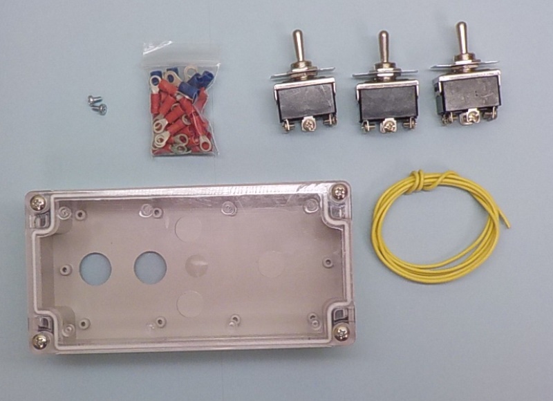
Plastic box, 3 Double pole double throw switches, 1 meter (40 inches) of 18 gauge wire (color may vary), 28 red terminal ring connectors, 6 blue terminal ring connectors, 2 additional screws (spares incase any are lost)
Tools Needed: Wire cutters, wire strippers, crimping tool, phillips head screwdriver, ⅛-inch flat head screwdriver, pliers, ruler with metric scale.
Tools Suggested: Multi-meter
Installing the switches
The first step is to insert the three switches into the pre-drilled holes on the control box.
To insert the switches:
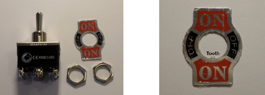
Disassembled components on the switch Metal plate- note the small tooth.
1. Unscrew the two nuts and remove the ON/OFF/ON metal plate from the switches. Insert the three switches through the clear plastic faceplate. The black box of the switch should be inside the control box, the toggle switch should stick up through the holes in the clear plastic faceplate.
2. Install the metal plate over the switch. Note the small groove on one side of the switch and notice the small tooth on the inner circle of the metal face plate. Match up the tooth so it fits into the groove.
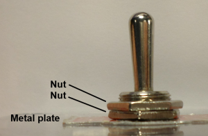
3. Screw one nut on to loosely hold the switch in place. Before tightening the first nut, twist the switch within hole so the metal plate reads ON/OFF/ON, not NO/OFF/NO. Consider how the controller is going to be held when twisting the switch to the proper orientation.
4. Once the orientation of the switch is correct, use pliers to tighten the nut and hold the switch securely in place. BE CAREFUL not to screw the nut on too tightly, as it can crack the clear plastic. The nut should be just tight enough so the switch does not twist on its own. Once the switch is secure, tighten the second nut down on top of the first.
Design note: The two bolts, and the ON/OFF/ON metal plate, are re-attached in a different order from what they are taken off the switch. The switch comes with a nut closest to the switch, then the metal plate, then another nut. When the switch is inserted through the clear faceplate, the metal plate goes on first, then the two nuts are screwed in on top of the metal plate to lock it down.
5. Repeat this procedure for the other two switches.

AngelFish Video: Mounting the Switches
Wire Preparation 1
The next step is to wire the back of the switches. Two wires will make the “X” on the back of each switch that allows the motor to run in two directions. Another set of wires allows power to be jumped from one switch to the other two switches.
Why do we need an “X” on the back of each switch? Review how Double Pole Double Throw switches work with the following presentations:
Video 2A: BASIC CIRCUITRY WITH A DPDT SWITCH
Video 2B: WIRING A MOTOR TO RUN IN FORWARD OR REVERSE
Video 2C: THREE SWITCHES CONTROLLING THREE MOTORS
To make the AngelFish ROV kit re-usable, ring connectors will be crimped on the ends of each wire. The ring connectors will be screwed onto the back of the switch to make a solid connection. To construct the wires:
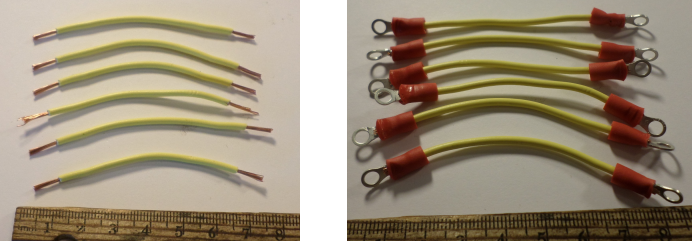
1. Cut six 6.5 cm lengths of 18-gauge wire. Strip .75 cm of wire of each end of the six wires. Note that the color of wire for wiring the back of the switch does not matter.
2. Crimp a #6 red ring terminal over each end of the six wires (see below for additional crimping instructions).
When crimping the ring terminals onto the end of the wire, it is important to get a secure, metal to metal connection. If the ring terminal is not secured properly to the bare metal wire, electricity may not flow through the connection and your controller will not work. To make a secure crimp connection:
1. Twist the .75 cm of stripped wires. Insert them through the hole in the red ring terminal until they emerge 1 mm out of the metal ring.
2. Use a crimping tool to crush the metal ring of the ring terminal over the stripped copper wire. The connection should be metal to metal so electricity can flow freely. The connection should also be physically secure so the wire cannot be pulled out of the ring terminal.
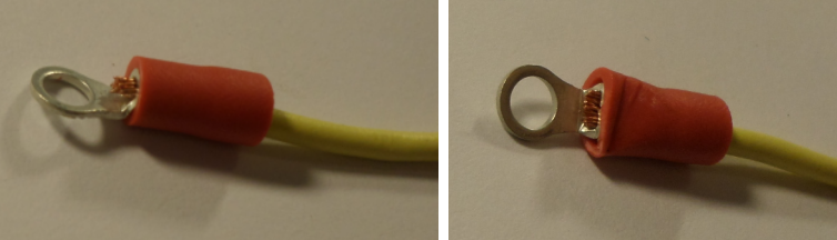
Copper wire emerging 1 mm beyond the metal ring. Metal ring securely crimped over copper wire.
A few other hints for good crimping:
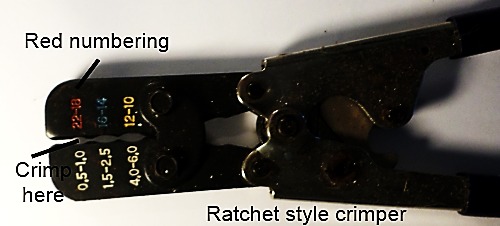
- Always use the red dot section of the crimper for the red terminal rings, blue for the blue terminal rings. The crimp tool may have red, yellow and blue dots/lettering. The color of dot corresponds to the color of sheathing on the terminal ring. The AngelFish uses red ring terminals over a single 18-gauge wire and uses blue ring terminals over two 18-gauge wires twisted together. Use the red dot/numbering section of the crimper to ensure a good crimp for a red ring terminal and the blue dot/numbering system section of the crimper to ensure a good crimp for the blue ring terminal.
- Use ratcheting crimpers. A ratcheting crimper will not release until a secure connection has been made. Note that it may need strong hands to squeeze the crimper so it releases.
- Give the wire/crimp connection a tug when the crimping is complete to ensure a secure connection. If the wire comes out when you tug on it, the connection was not good. Use a new red ring terminal (throw out the old one) and try again. A few extra terminals are included in AngelFish kit, as is some extra 18-gauge wire, to use when crimping problems occur.
AngelFish Video: Preparing the Wires 1
Video: Using a Ratcheting Crimper
Design note: VERY IMPORTANT. The most common cause of failure in the AngelFish control system is a wire that is not properly crimped. If the metal ring was not securely crimped over the copper wire, electricity may not flow through the connection. Also, the wire may also fall out of the ring terminal if not securely crimped, again stopping the flow of electricity through the circuit. MAKE SURE ALL YOUR CRIMPS ARE SECURE. If a switch is not operating, the first troubleshooting technique should be to re-examine all the connections to make sure they are properly crimped.
No wire should be exposed outside the red terminal ring. Exposed wiring may connect with other metal and create a short circuit. This can lead to vehicle malfunctions and sparks/fire/melting components. If wire is exposed outside the red plastic covering on the terminal, shorten the amount of wire being stripped and re-crimp the terminal.
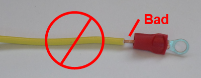
Very bad connection. The exposed wire outside the plastic covering can cause a short circuit.
Use a multimeter to test whether your crimps are good and whether electricity will flow properly from one end of the wire to the other. Use the resistance (ohm) setting to test the resistance from the end of one terminal crimp to the end of other terminal crimp. The resistance reading should be 0.0 ohms for each length of wire. Note, your multimeter may be a different brand, but the principles are the same.
AngelFish Video: Testing the Wires 1
Making the “X” on the back of each switch
The backside of each switch has 6 poles or posts. These posts are numbered 1 through 6. The six wires with ring terminals will make an “X” on the back of each post, which allows the motors to run in both directions. To make the “X”:
1. On one switch, carefully remove screws from post 1, 3, 4 and 6. Be very careful not to lose these screws, set them aside in a safe location where they will not be lost.
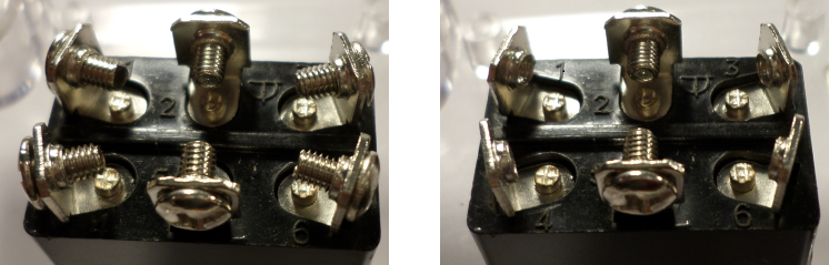
Back of switch showing 6 posts. Screws on post 1, 3, 4 and 6 removed.
2. Take 1 screw and wire with crimps on both sides. Push the screw through the red ring terminal and screw it into the post #1. The ring terminal should be between the head of the screw and the post.
3. Take another screw and push it through the ring terminal on the other end of the wire. Screw it into post #6. At this point, the wire should connect post #1 to post #6.
4. Using a second wire with crimps at both ends, screw one end into post #3 and the other end into post #4.
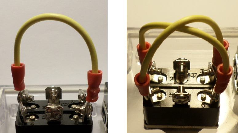
Wire connecting post #1 to post #6 Wires connecting post #1 to #6, post #3 to #4.
5. Repeat this process on the other two switches.
Hint: It may help to rotate the switch a small amount in the hole through the clear plastic faceplate when using a screwdriver to install the screws.
AngelFish Video: Attaching Wires to the Switch 1
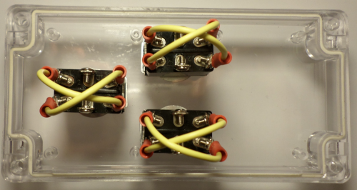
The three switches with “X” wires on the back of each.
Once the wires are installed on the back of a switch, use a multimeter to test resistance from one post #1 to post #6 and post #3 to post #4. Set the multimeter to resistance (ohms) and touch the multimeter lead to the head of the screw on one post to the head of the screw on the other post. The resistance reading should be 0.0 ohms for each length of wire.
AngelFish Video: Testing the Wires 2
Wire preparation 2
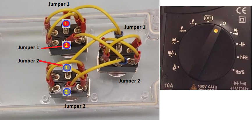
The next step is to wire power jumpers between the three switches. The middle posts, posts #2 and #5 are the posts for bringing power in (red positive, black ground). Jumpers between the switches will allow power brought into one switch and transferred to the other two switches. To construct the jumpers:
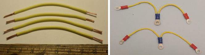
1. Cut four 9 cm lengths of 18-gauge wire. Strip .75 cm of wire of each end of the four wires.
2. Take two of the 9 cm lengths of wire, set them side by side, and twist one pair of stripped ends together. Crimp a blue ring terminal over the joined ends. Take the other two 8 cm lengths of wire, set them side by side, and twist one pair of stripped ends together. Crimp a blue ring terminal over the joined ends. Make sure this is a secure crimp connection for both crimps!
3. Crimp a red ring terminal over the four remaining single ends of the wires.
Design note: Blue terminal crimps are for 14 to 16 gauge wire. Two 18 gauge wires twisted together approximate this larger wire diameter. If using a ratcheting crimper, make sure to crimp using the blue section.
AngelFish Video: Creating the Jumper Wires
Use a multimeter to test whether your crimps are good and whether electricity will flow properly from one end of the jumper wire to the other. Use the resistance (ohm) setting to test the resistance from the one red terminal crimp to the other red terminal crimp. The resistance reading should be 0.0 ohms for each length of wire.
AngelFish Video: Testing the Jumper Wires 1
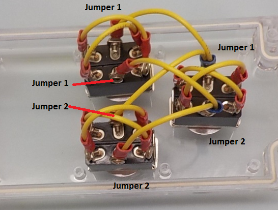
Attaching the power jumpers
The power jumper wires attach to the middle posts of the three switches. The red/black power wire will bring in electricity from a power supply to one switch. The jumpers will transfer the power to the other two switches.
To connect the jumper wires:
- Remove the screws from post #2 and post #5 on each of the three switches. Be very careful not to lose these screws, set them aside in a safe location where they will not be lost.
- Using one jumper wire, attach the three ring terminals to the center post on the left side of each switch (note that this may be post #2 or #5).
- Using the other jumper wire, attach the three ring terminals to the center post on the right side of each switch.
AngelFish Video: Attaching the Jumper Wires
Once the wires are installed on the back of a switch, use a multimeter to test resistance from one post #2 where one red terminal crimp is connected, to post #2 where the other red terminal crimp is connected. Repeat this resistance test for posts #5 where the red terminal crimps are connected. Set the multimeter to resistance (ohms) and touch the multimeter lead to the head of the screw on one post to the head of the screw on the other post. The resistance reading should be 0.0 ohms for each length of wire.
AngelFish Video: Testing the Jumper Wires 2
Attaching stress relief
Two holes are drilled in the plastic box. The ROV tether will pass through one hole; the power wires will pass through the other hole. Both wires will pass through stress relievers. The tether wire will pass through the 3/8-inch long stress relief. The power wire will pass through the 3/8-inch long short stress relief. To install the stress reliefs:
- Unscrew the long stress relief into the three components. Push the plastic bolt through the hole closest from the center of the controller. The hexagonal part of the bolt should be flush against the outside of the control box, with the small threads protruding through the hole in the control box.
- Screw the small nut onto the small threads until the bolt is tightly secured to the control box.
- Loosely screw the stress relief (long) onto the larger threads.
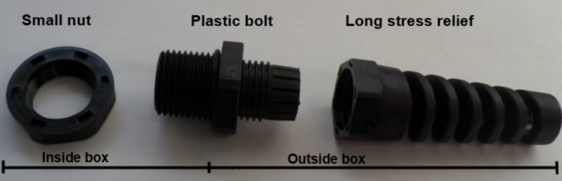
Disassembled long stress relief.
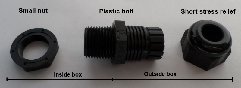
Disassembled short stress relief.
- Unscrew the short stress relief into the three components. Push the plastic bolt through the hole closest from the center of the controller. The hexagonal part of the bolt should be flush against the outside of the control box, with the small threads protruding through the hole in the control box.
- Screw the small nut onto the small threads until the bolt is tightly secured to the control box.
- Loosely screw the stress relief (short) onto the larger threads.
AngelFish Video: Installing the Strain Relief

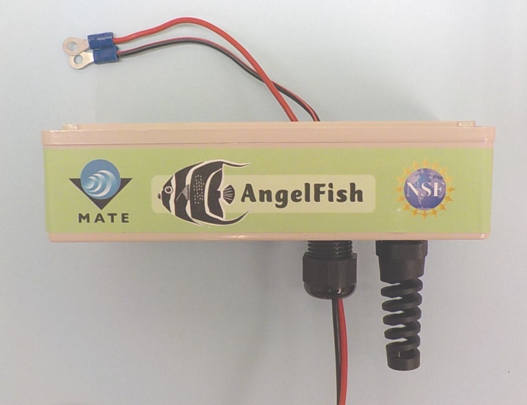
Side view of control box with both stress reliefs installed.
Connecting Power to the Control Box
If you have not made your Power Wires yet, go to: POWER SYSTEM: CREATING YOUR POWER WIRES
When the power wire system is completed, you can connect it to the control system. To connect the power wires to the control system:
- Push approximately 30 cm of the red and black wire (the side without the fuse) through the short stress relief. The wire should be pushed through from the outside to the inside of the control box.
- On the 30 cm of wire inside the control box, pull apart 8 cm of the red wire and black wire (separate the two joined colored wires). Strip 0.75 cm from the end of each wire.
- Crimp a blue ring terminal over the end of both the red wire and black wire.
- Set your clear plastic faceplate upside down to access the bottom of the switches. Carefully unscrew the center, right post (post #2 or post #5, on the right side of the switch as you are looking down at it) screw on ONE switch only. This post should already have a jumper wire attached.
- Attach both the jumper wire and the blue power wire to this post. Use the screw to secure both ring terminals and both sets of wires to the post.
- Carefully unscrew the center, left post on the same switch. This post should have the other power jumper wire attached.
- Attach both the jumper wire and the black power wire to this post. Use the screw to secure both ring terminals and both sets of wires to the post.
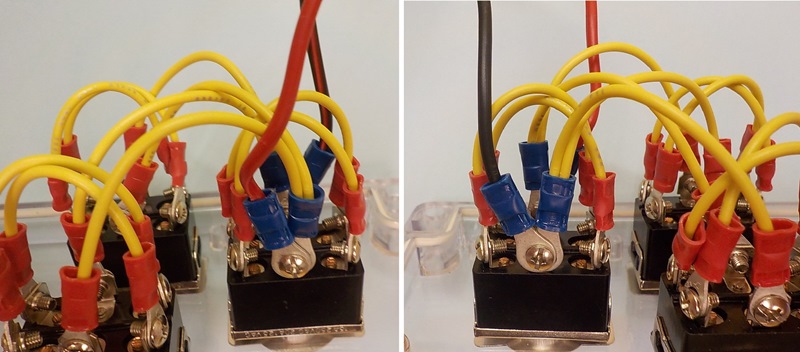
The red power wire attaches to the middle post of one switch. The black power wire attaches to the opposite middle post of the same switch.
Design note: The jumper wires will bring the 12V+ from the red power wire to all three switches. The jumper wires will bring the GND from the black power wire to all three switches. Make sure that the red and black power wires are attached to the two different jumpers.
AngelFish Video: Powering the Control Box
Once both the red and black wire are secured to a switch, pull the any excess power wire back out through the small stress relief. Tighten the small stress relief nut over the threads to secure the power wire in place.
Design note: The side of the switch that the red and black wires attach into controls polarity; which way the motor runs when you push your switch forward. If all three of your motors run in the opposite direction as desired, you can switch the sides of the red and black wires, and the polarity will change (motors will now run in the opposite direction).
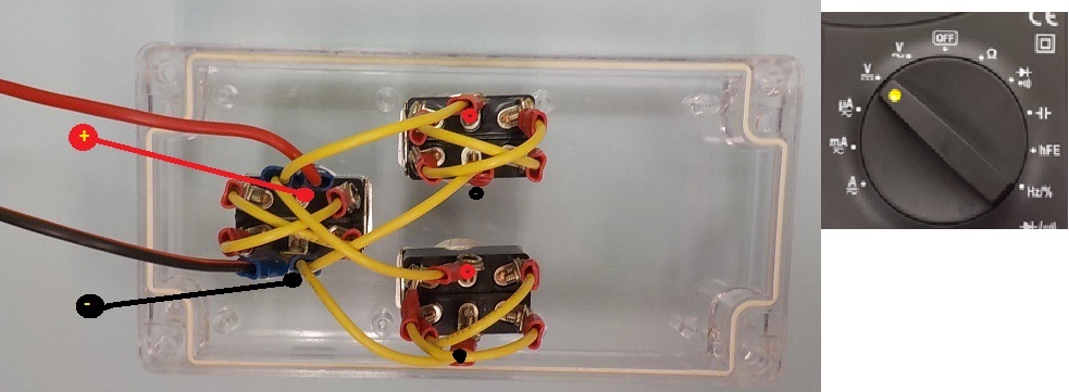
Testing the Power system
Once the power wires are installed, use a multimeter to test the power system by tracing the voltage to each switch. Set the multimeter on DC volts and connect the red/black power cord to a power source. On one of the switches, touch the red lead to the middle post where power comes in, and the black lead to the opposite middle post (posts #2 and #5). The voltage readings should be 12 volt nominal (12 volts to 14.1 volts depending on the power source being used).
AngelFish Video: Testing Power in the Control Box
If you have good voltage reading (same as source voltage) on all three switches, your control box is complete. Don’t close up the box yet, however, there are a few more wires to add.
Updates:
September 26, 2020. MG. Added videos for how-to and testing.