3/15 - score: 8.0/10 - good but missing a week
2/22 - score: 8.5/10 much better progress. Still a few gaps (2/11-2/19), but fuller picture of what you’re doing. Pieces that you still need: wiring diagrams, overall system diagram, sample data of what a dead/full/charging battery looks like. Get these in your upcoming poster draft and include them here as well
2/4 - score: 7.5/10 better progress than last, but still some pieces missing. Pretty big gap from 1/29 to 2/3... please fill in. Also, you need a visual to quickly convey your overall idea, with all of the components in place. nice work on LCD screen - i wants to see!
1/22/13 - score: 6/10 include graphs/data you have gathered, a summary of your proposal should go here as well. Need more detail about what you have done in these first 2 weeks
P IT
M ANAGEMENT
S ySTEM
I would like to create a program to run on a low power/low cost computer that manages all aspects of a FIRST team’s pit at a regional. It would fetch and display the match schedule and bumper colours, as well the current seed and points for the team. It would also include the battery charging system and measure and display the voltages of all connected batteries, as well as logging loaned out and borrowed tools and supplies. It would also interface with a tablet device, either directly or through a web server to display a pre-match checklist that the team will use to prepare the robot for each match, and display the status of the robot, be it in match, in pit, ready to queue, or queuing.
I imagine that I will initially try to create something relevant to my project that will fail to do anything and will then proceed to begin my research. The first bit of which will be how to determine what the voltage of a battery would be under load, and possibly if it is possible to do that whilst the battery is charging. At that point I will pick a computer platform that would be used in the final project, be it a raspberry pi or simply a laptop or anything else, and will then cobble together some code to read the battery voltages and display them in a text box. That will most likely be done with java. I would then research how to fetch data from the internet and how to display it on a screen in pretty tables with colours. Afterwards I will program the thing to actually do that. Once that is complete I will research how to interface with a tablet device or a simple web server. Then there will be more frantic coding and possibly making the whole system look half-decent.
I will need a computer, some wood, screws, simple electrical components. I’m guessing the single part that will carry the majority of the cost will be the small low power/low cost computer. It will cost approximately $35. I would give a healthy cost estimate for the project to be around fifty or sixty dollars, all things considered.
I will mainly need programming mentoring help, but possibly a tad bit of electrical help as well. I’m not sure how well this would work, or if it would even be acceptable, but my father is a computer programmer and works with electronics, so he could probably mentor me.
Materials List:
Quantity | Price | Type | Specs |
1 | €30 | Arduino | Uno or Duemilanova |
1 | Ø | Computer | Personal Laptop (Testing) |
1 | $35 | Computer | Raspberry Pi (System) |
1 | Ø | Linux | Raspbian |
6 | Low | Resistor | 1M |
6 | Low | Resistor | 470K |
1 | Ø | LCD Kit | Panel, Inverter, Input Converter, 12V PSU, Keypad |
1 | IDK | Case | Raspberry Pi |
1 | IDK | USB Hub | Powered |
6 | 50c | Opto-Isolator | Digikey 160-1300-5-ND |
1 | IDK | Adapter | USB WiFi Adapter |
1/17/2013
I have begun researching various methods of testing battery voltage while being able to interface with a computer. I have found a company in Europe which sells such circuits, however I am still trying to find a schematic to see if I can build the circuit myself.
http://www.digital-measure.com/html/voltmeter.htm
I would, however, like to be able to measure the voltage of the battery while it is charging, and do not think a simple voltmeter will work for that [NEEDS TESTING] and am thinking that perhaps a current measurement system that could be used to extrapolate the voltage might be better.
1/22/2013
I would like to explore trying to measure the current of the charge in order to extrapolate the voltage, but need to do significant research. I am seeing the term “hall effect” come up on multiple resources. Maybe I should research it. I can use a clamp on hall effect sensor to measure the current, but I don’t know how I would extrapolate that to voltage.
A fully charged 12v lead-acid robot battery will be around 13.5 to 14 volts. I still need to test hooking up a voltmeter to a charging battery and recording the voltage.
1/24/2013
Battery Number | Raw Voltage | Charging Voltage | Stable Voltage |
1 | 12.98 | 13.10 | 13.06 |
2 | 12.72 | 12.90 | 12.79 |
4 | 12.13 | 12.29 | 12.20 |
5 | 12.71 | 12.90 | 12.78 |
As it appears, it is possible to measure the battery voltage while it is charging. The battery voltage does, however, “bleed” voltage for about 15 to 20 seconds, before reaching a relatively stable voltage. In most cases the voltage dropped around a tenth of a volt. And even if I cannot find a way to determine the correct stable voltage, i will still be able to measure the relative differences between all of the batteries hooked up to the system and be able to select the most charged one.
I do believe, however, that a direct voltmeter will work.
I think the best way to measure the voltages will be with an Arduino. The battery will feed to a voltage divider such that a fully charged battery will be close to five volts. as the battery voltage drops from 13 or 14, that feeding into the Arduino analog inputs will drop from five. The Arduino will also be easy to pair with and feed data to a more powerful computer, such as a Raspberry Pi.
1/25/2013
Voltage dividing formula:
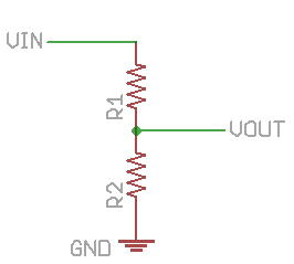

I would like to be able to bring 14v down to 5v. So, 5=14(x/(x+y)). And then, 5x+5y=14x, and then, 5y=9x, so y=(9/5)x, where x is R2 and y is R1.
If I were to make y = 1 million ohms, so as to also highly reduce the current, x = 555 thousand ohms. I don’t think that is going to work. R1 as 1 million ohms and R2 as 470 thousand ohms will work, and the maximum output will not quite be 4.5 volts. That should work nicely. I do not know, however, if I will need special resistors because I am attaching them to a very high current, lead acid car battery.
1/26/2013
Voltage dividing does work and I can read the values with an Arduino.
Battery Type | Voltage | Value |
6 AA | 8.67 | 583 |
Robot | 11.95 | 805 |
I was using a 1M and a 470K resistors. When attached to an ohm-meter they read as .955M and .460M. Amperage with those resistors in the order of microamps, so the arduino should be safe.
I am thinking that Processing might be the best language to write all of my code in. It can interface with an Arduino, as because it is based off of Java, is supposedly relatively easy to use to do graphical analysis.
1/29/2013
I have begun the process of programming. I am initially trying to simply talk to the Arduino, but need to research more into printing lines with Processing. My sample code so far follows:
import processing.serial.*;
import cc.arduino.*;
Arduino arduino;
int ledPin = 13;
void setup()
{
println(Arduino.list());
//arduino = new Arduino(this, Arduino.list()[0], 57600);
//arduino.pinMode(ledPin, Arduino.OUTPUT);
}
/*
void draw()
{
arduino.digitalWrite(ledPin, Arduino.HIGH);
delay(1000);
arduino.digitalWrite(ledPin, Arduino.LOW);
delay(1000);
}
*/
Arduino.list();
analogRead(0);
analogRead(1);
analogRead(2);
analogRead(3);
analogRead(4);
analogRead(5);
*/
I have yet to comment anything, as once I get talking with the Arduino I will almost certainly entirely rework this portion of code. The Arduino.list() command is used for returning Arduino devices plugged into serial ports, and is what I am currently struggling with.
Using the code:
import processing.serial.*;
import cc.arduino.*;
void setup()
{
println(Arduino.list()); //Displays attached Arduino devices
}
Processing reads and displays the attached arduino devices. On my laptop it attaches to “COM6.” the only issue is that it will likely be different on my desktop, but I will address that if I ever use it for programming.
2/3/2013
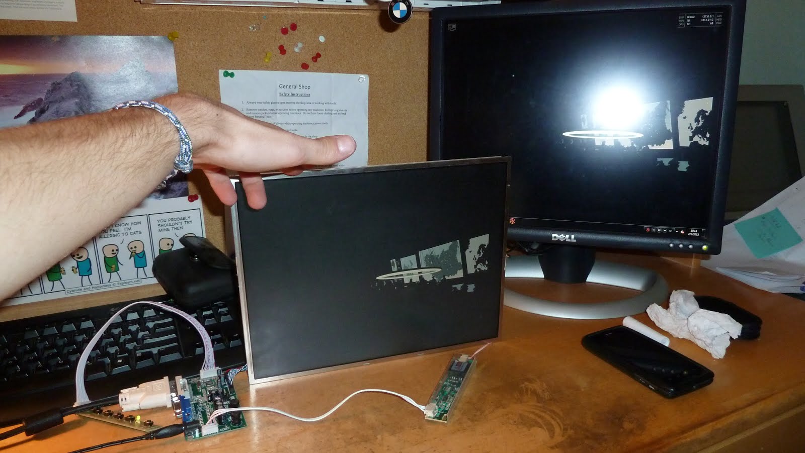
I have set up a laptop lcd screen with some circuitry to take a standard computer DVI/VGA and use it to drive an lcd panel.
2/4/2013
I have written and tested all the code that should be required for reading and writing the voltage of six 12v batteries.
import processing.serial.*; //I’m not actually sure if need this library, but it works the way it is
import cc.arduino.*; //This is the library that allows processing to communicate with the arduino
PFont f; //Just some Processing jargin to allow me to type text to a window
Arduino arduino; //Initialises the Arduino
void setup(){
size(200,200); //This is the size of the window I am printing to. In due time I will expand this to the size of the monitor I am going to use
f = createFont("Arial",16,true); //More font stuff for printing text
arduino = new Arduino(this, Arduino.list()[1], 57600); //This Actually sets up the Arduino
String bat0 = new String("bat0"); //Don’t mind me; I’m just declaring the strings that will later have the battery voltages associated with them
String bat1 = new String("bat1");
String bat2 = new String("bat2");
String bat3 = new String("bat3");
String bat4 = new String("bat4");
String bat5 = new String("bat5");
}
void draw()
{
background(255); //These next three lines declare the colors for the window and font, and the size and font to be used in this draw() whatever its called
textFont(f,16);
fill(0);
int bat00 = 1023; //I am declaring my battery voltage integer here
bat00 = arduino.analogRead(0); //Here, it gets assigned the value from the Arduino’s analog in
bat00 = bat00 / 73; //Here, I do some simple math to convert the 0-1023 for a voltage 0-5 to a voltage 0-14. Basically, what I did was divide 1023 by 14, and that number was 73. It will need tweeking for the variability in resistors, and the fact that 5/14 isn’t quite the ratio for my resistors. That 73 is just a relatively good placeholder.
String bat0 = str(bat00); //The str() function converts the integer batxx to a string so I can print it.
text("Battery 1 voltage is " + bat0 + "v",0,16); //Finally, the moment of truth and justice; I am printing the battery voltage, such that it reads: “Battery x voltage is xx.xv”
int bat11 = 1023;
bat11 = arduino.analogRead(1);
bat11 = bat11 / 73;
String bat1 = str(bat11);
text("Battery 2 voltage is " + bat1 + "v",0,36);
int bat22 = 1023;
bat22 = arduino.analogRead(2);
bat22 = bat22 / 73;
String bat2 = str(bat22);
text("Battery 3 voltage is " + bat2 + "v",0,56);
int bat33 = 1023;
bat33 = arduino.analogRead(3);
bat33 = bat33 / 73;
String bat3 = str(bat33);
text("Battery 4 voltage is " + bat3 + "v",0,76);
int bat44 = 1023;
bat44 = arduino.analogRead(4);
bat44 = bat44 / 73;
String bat4 = str(bat44);
text("Battery 5 voltage is " + bat4 + "v",0,96);
int bat55 = 1023;
bat55 = arduino.analogRead(5);
bat55 = bat55 / 73;
String bat5 = str(bat55);
text("Battery 6 voltage is " + bat5 + "v",0,116);
}
One thing I have not accounted for is decimal places. Integers do not have them, and a float will have lots. My dad has told me that there is a way in Java to restrict a number to only one decimal place, so that is probably what I will explore next. Oh, and before I forget, I am currently just using potentiometers in place of batteries, but will hopefully swap them out for the real deal sometime soon.
2/6/2013
I am currently trying to get processing to display the text window fullscreen on my secondary monitor. It shouldn’t be that important for the final design, because it will be the only monitor, but it would make testing more convenient and would be useful to know. By running the sketch in “present” mode it automatically makes it full screen on the default monitor, but what I have found seems to indicate that in processing 1.5.1 there is no way to change which monitor is the default monitor. The problem is that I have not gotten the arduino to communicate with processing 2.0b7. But like I mentioned above, it is not that imperative to have that feature.
In terms of dealing with decimal places, the nf() function acts in a very similar manner to the str() function, but I can use it to define the number of digits to the left and right of the decimal point. But because I am now dealing with decimals, I needed to change the int batxx to a float.
Before:
int bat00 = 1023;
bat00 = arduino.analogRead(0);
bat00 = bat00 / 73;
String bat0 = str(bat00);
text("Battery 1 voltage is " + bat0 + "v",0,16);
After:
float bat00 = 874;
bat00 = arduino.analogRead(0);
bat00 = bat00 / 73;
String bat0 = nf(bat00,2,2);
text("Battery 1 voltage is " + bat0 + "v",0,16);
2/7/2013.
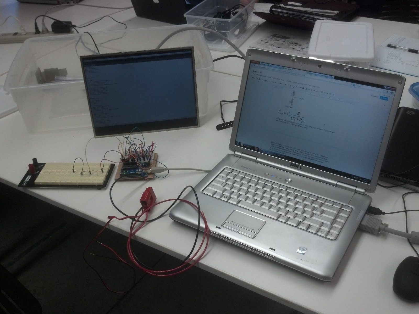
I have begun to wire a breadboard with resistors and connection points for batteries, as opposed to the potentiometers I currently have set up as my “batteries.” I have started to solder battery quick disconnects that have an extra pair of leads for hooking up to the breadboard.
2/11/2013
The battery/charger/Arduino interface cable works wonderfully. The first version of it had header pins too large for an Arduino/breadboard, so I had to rework those, but it is now fixed. With the circuit for measuring the voltage of one battery it works, and I calibrated the code but dividing the analog value (0-1023) by 61.84. This number will. of course, be different for each voltage divider, based on the precision of the resistors.
I may want to look into another screen monitor, because as the one I have is about 10 years old it is not very bright nor are the colors particularly good, but most importantly both the sideways and heightways viewing angles are very limited. The screen has to almost be oriented straight towards me in order to easily read the numbers. I do though, have several extra monitors, so I may be able to work something out.
I have also placed an order for a Raspberry Pi, which should arrive at some point in the future.
2/19/2013
Raspberry Pi came in the mail today. Need to start trying to format it with the OS. Also, I’m not sure how retrieving competition data will work out. There are websites and mobile applications which do such, but I do not know where they retrieve data from. I need to do some data mining and find out. I have installed the Android SDK to try to analyze one such app, FRC Spyder.
2/20/2013
I have successfully loaded the OS (Raspbian) onto my Raspberry Pi and have begun downloading packages and setting up processing on it. Natively, processing won’t run on its ARM processor, but there are a few file changes that can be made so that it will run.
2/22/2013
I have got Processing working on my Raspberry Pi. The whole machine is very slow, but that is to be expected; it is not particularly powerful, after all. I’ve run some sample code to just write text in a window, but have not tried to run what I’ve written for battery voltage monitoring.
For downloading match data, I can view data in an xml table from http://www2.usfirst.org/20XXcomp/events/YYY/matchresults.html, where 20XX is the year, and YYY is the 2 or 3 letter regional code, SJ for Silicon Valley, and SAC for Sacramento. In order to decode the tables, however, I will need an XML Parser.
2/24/2013
So as it turns out, JAVA has a built in XML Parser, JAXB. I have tried to run some sample code in processing I obtained from here, http://wiki.processing.org/w/XML_parsing_with_JAXB. I was not, however able to run it successfully. I was getting an odd error message. Once I get it working, though, I am still not sure how to get the data I want. How the tables are set up, I need to identify which tablerow has “852” in it, then retrieve the information tabledatums 1 and 2 from that tablerow, and figure out whether the “852” is in the 3rd, 4th, or 5th tabledatums, or in the 6th, 7th, or 8th tabledatums.
I’ll figure something out.
2/26/2013
I have successfully parsed and displayed the contents of the webpage I will retrieve data from the www2.usfirst.org webpage above. It didn’t work with JAXB, but there is another parser, called HTML Parser, that works nicely. It runs on the Raspberry Pi, but is very slow, on account of the Raspberry Pi’s underpoweredness. The one problem with retreiving match information and scores, et cetera, is that, starting this year, the venues will not have WIFI. I can download match times and team arrangements beforehand, but the times change, and it would be nice to know the scores. I can, however, use a phone to create either a wifi or bluetooth hotspot, that the Raspberry Pi will utilise to refresh match data whenever phone is in the pit.
2/27/2013
I have successfully tethered my iPad to my Droid 4 ICS phone via bluetooth, and the internet on the iPad works nicely. It isn't the fastest thing in the world, but it shouldn’t matter, is I am merely retrieving text and only a few low resolution images. Now I will just need to get it to work with my phone and Raspberry Pi.
2/28/2013
Lo and behold! http://blog.kugelfish.com/2012/10/look-ma-no-wires-raspberry-pi-bluetooth.html
But if I could run Android OS on it, that would be infinitely better. Tethering would be easier, and Processing can run on Android, though I’m not sure how well. At the same time, Processing is quite slow on the Raspberry Pi, so it can’t be slower, can it? I do need a bluetooth shield, however.
3/3/2013
I’m not sure if bluetooth tethering is the way to go. Bluetooth is often flaky, and it would require me to re-connect my phone and the computer each time I leave and return to the pit. Setting up a small WiFi hotspot should be OK, and would work much better.
On a different front, I think I have a solution for the issues regarding my battery voltage sensors and their common ground. I am going to electrically isolate the batteries from the arduino using opto-isolators. That will be safer, and should help with some of the bleeding I saw. I am also going to put another 1M Ohm resistor between each opto-isolator ground and the arduino ground.
3/8/2013
I printed a case for my Raspberry Pi. It doesn't quite fit );
Update 3/9/2013 I made it fit with some sanding/dremeling
Publish Link:
https://docs.google.com/document/d/1mmpST97AAkXmYL8IHxarTK46gLsFaGLwgCGPsZa5Mr4/pub
4/25/2013
All systems are go; I am currently working on integrating the various individual UI components together.
Poster
https://docs.google.com/file/d/0B23xty-ooj-ueFg2blQwclU0a2c/edit?usp=sharing