Experiment 0: Assemble a Motor

The motor in this design uses six coils that remain in place.
By changing the current through the coils, they can remotely spin a disc with 8 magnets. On both sides of the disc with coils (the stator) there is such a disc with magnets (the rotor).
You can customize this design. All design files are editable in FreeCAD. The parts are made in such a way that they fit together several times. You could also make a motor with two stators and three rotors using the same parts.
What you need:
- A 3d printer with sufficient filament.
- A stainless steel rod with a diameter of 8mm (minimum 12 cm long).
- Three ball bearings of 8x22x7 mm (inner diameter x outer diameter x thickness).
- 16 disc magnets with a diameter of 20 mm and a thickness of 8 mm
- copper wire with a diameter of 0.2 mm (preferably not thicker!)
- Metal tubes with a diameter of 0.4 mm (available at the model shop)
optional: - Dupont sockets with 3 pins and cables attached.
- Hall sensors (Honeywell SS411A bipolar)
The rotors: stick magnetsmagnets

The current design uses discwith a diameter of 20 mm and a thickness of 8 mm. You need 8 of that per rotor. You can click them into the rotor, but stick them with epoxy, so that they are not thrown out of the motor.
First click the magnets into the stator with one pole to the top and glue them on. Then insert the magnets with the other pole up into the other openings in the rotor.
The shaft is attached to the rotors and stays in place thanks to ball bearings. These are bearings of 8x22x7 mm (inner diameter x outer diameter x thickness). Not entirely coincidentally the same size as the bearings in a fidget spinner. For the axle we take a rod with a diameter of 8 mm. Also glue the rotors to the shaft with epoxy.
The stator: winding coils
The fixed part of the motor, the stator, contains six coils. You have to wrap this yourself around a bobbin that you can also print. Approximately 36m of copper wire with a diameter of 0.2 mm goes on a spool. It is useful if you use it for several parallel wires. For example, you can wrap 6 wires of 6m side by side around the bobbin, but also 12 wires of 3m or 9 wires of 4m. With this you can adjust the resistance of the coils, so that the power of the motor also changes. The lower the resistance, the higher the power.
1. Tension the wires
Place two rods somewhere at the desired distance from each other and tension the copper wire between them. If you have walked back and forth nine times between two posts 4 m away, you will have nine 4 m wires.
2. Wrap the wires on the bobbin
The bobbin is designed to fit snugly into the holes of the stator. First wrap a piece of cling film around the bobbin. At one end, insert the threads through the hole in the bobbin and wrap the rest around it. A little bit of craft glue between the threads will keep the coil tightly in place.
3. Push the spool, thread and all, into the stator.
Allow the glue to dry, then remove the spool, leaving the spool behind. Wind the next coil. If you print two spools you work faster. Fix the bobbin with a screw clamp.
Make sure that the winding direction is the same for all coils. If you have wound the bobbin the wrong way around, you have to press it the other way around in the stator.

4. Connect the ends of the coils to the correct inputs
. For three coils, the output of one coil goes out into the channel together with the input of the next coil (see picture). The output of the third coil goes to the input of the first coil.

5. Solder the coils to the inputs.
Remove the lacquer from the copper wire with a lighter or fine sandpaper. Insert the copper wire into a fine metal tube that fits into the outlet and fill that tube with solder. Be careful not to get the tube so hot that the rotor melts. It works best to heat the end of the tube with a small gas lighter, until you can melt a wire of solder in it.
Bonus: 6. Hall sensors.
Above the recess for the metal tubes where the entrance to the coils is located, there is a rectangular hole. That exactly fits a JST socket with three connections. Here you can click Hall sensors (type SS411A), so that you can connect the motor to an intelligent controller. Just glue them down if you do.
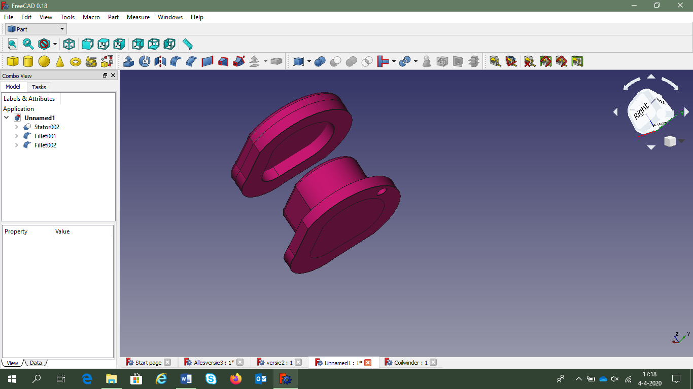
… And everything click together
The motor consists of four different parts: the rotor part, the stator part, the ring for the housing and an end ring. Click all this together as in the picture below. This design also uses the stator part as a closure.
Floor
When you have put this motor together you know exactly what such a motor consists of. You are now able to design a motor yourself. This engine is designed in FreeCAD, but it is also possible in Sketchup or Tinkercad.


Experiment 1: Generating an AC voltage ...
Introduction
The motor you just built runs on AC. You not only control this motor by sending a current through it, but this current also has a certain frequency. And even if you turn the shaft of the motor, it produces an alternating voltage. Then you actually use the motor as a generator.
In the figure below, the rotor isin each case a step of 15° rotatedcounter-clockwise.
In each panel there are always two openings opposite each other that exactly capture a north pole or a south pole of a magnet. If we madeafter these six 15stepso another panel, it would look exactly like the first panel.

We can also plot this in a graph. We set the magnetic flux (Ψ) on the vertical axis and the rotation on the horizontal axis. We can see here that a period90o lasts.


Because change in magnetic flux causes a voltage, we can now also make a voltage graph. This is the slope of the flux graph.
But that's the theory. In this experiment you put an external motor on the shaft to see if it actually produces such a nice AC voltage.
Method
Drive the generator with an external motor (a drill or screw top is fine). See if you can visualize an AC voltage with a data logger (Coach, Pasco, Arduino, Vernier) or an oscilloscope. Measure the voltage on the coils against ground (those pins on the side of an outlet).
Measure at different speeds. Record the speed of the motor, the frequency of the signal and the amplitude of the voltage in the table on the next page.

Results
Speed in revolutions per second | Frequency of the voltage in Hz | Amplitude of the voltage in Volts |
Make graphs in which you plot the frequency and amplitude of the alternating voltage as a function of the speed.

Conclusion Do
your observations agree with the theory? Can you explain differences?

Experiment 2: Torque characteristic
You can show the specifications of a motor in a torque characteristic. This is a graph in which the force that the motor delivers is plotted against the speed at which the motor rotates. Because the power of the motor also depends on the distance to the pivot point, we express that force in Nm. Then we don't call it force, but torque (symbol τ). Because the speed also depends on the distance to the pivot point, we measure the speed (symbol ω).
Modern electric vehicles have electric motors that can run at different voltages and frequencies. For every voltage and frequency there is an optimum combination of power and speed. You will find this optimum as a top in a torque characteristic.

The software in vehicles adjusts the frequency with which the motor is controlled so that it always delivers the maximum torque.
In this practical, you make your own torque characteristic at a fixed frequency and voltage. If your classmates take a different frequency, we as a class could make a three-dimensional graph.

Method
Record the voltage |
Write down the frequency and voltage with which you are going to control the motor in the boxes to the right. First measure the speed of the idle motor.
How do you measure speed?
Write down the frequency (in Hz) with which you control the motor. |
You determine the speed with a stroboscope. Attach a piece of
tape to the shaft of the motor and find the highest possible frequency at
which the piece of tape appears to be stationary. If you sit too high you will see two pieces of tape standing still. Then you have probably set the speed on the stroboscope twice too high.
You have just measured the speed of the motor at a load of 0 Nm. Can you already fill in the results. Now the rest.
How do you measure torque?

How much power does such a motor deliver? That depends on how hard you slow it down. If you slow down the engine harder it takes more power to turn.
The simplest brake is a weight on a cable that you hang over the axle. In order to be able to calculate the torque correctly, we make a bobbin around the axis of which we know the exact radius.
If the cable is simply hanging perpendicularly, the only force pulling on the cable is the weight of the mass hanging from it. If you hang the cable over the bobbin, the friction force on the motor is added. For example, you can measurewith a force meter
how much power a motor delivers. Multiply that by the radius of the bobbin and you get the torque.
Record the radius of the bobbin around the motor axis. |
Write down the weight that hangs on the cable. |
Record your results in the results table.
Results
Speed per second | Measured friction force | Calculated Torque |
Create a graph of your measurement data. With a title and an axis format and so on. You know.

Conclusion
Try to estimate where you think the optimum torque is. At what speed is that? Indicate this in the graph.
Deepening
Try to find out from several torque characteristics how a smart controller must adapt its frequency to the angular speed in order to always generate the maximum torque.