Recently a kit has become available via ebay and other Chinese online vendors which simplifies creation of a direct sampling mod with the usual RTL-SDR dongles that folks have been using to “play” with low priced SDR. Fortunately the kit is well supplied with all the parts you need -including the RTL2832U dongle at a pretty good price (about $30 CAD shipped)
Unfortunately there are no included assembly instructions. And while the blog entry at:
http://bbs.kechuang.org/read-kc-tid-62913-1-1.html does help, it’s in Chinese. While the Google translate translation is hilarious it is not particularly helpful if you don’t have some experience putting together RF projects or kits.
What follows, is - I hope - enough of a basic guide to help the moderately experienced hobbyist put this together. Most of the photos were ripped from the above blog.
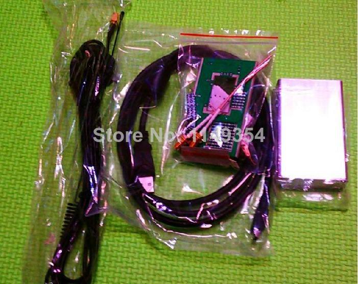
1) After an inventory of your kit you will likely find that you are supplied with
1-Dongle
1- Breakout board
1- Nice Aluminum case
1- Antenna with coax and connector
2- SMA female connectors (note that the older kits had hunks of coax with connectors)
A collection of surface mount capacitors and resistors (likely one more of each kind than you need) and one LED (the marked side goes to the ground plane [-])
1- single surface mount inductor - yes it looks the same as the capacitors but the package is marked
1- fine wire and 2 pieces of thick wire
1- tiny ferrite toroid appropriate for HF frequencies
1- 3 pin connector with jumper
1- mini usb connector
Through the hole components: LED, Three capacitors
Before you go on - you must have some experience soldering surface mount components. If not then get educated and then practice on some (maybe on the extras in the kit using the “free” breadboard areas that are left on the kit board) - for instance you could have a look at some videos like:
http://youtu.be/3NN7UGWYmBY
go ahead and have a look, I will wait for you here.
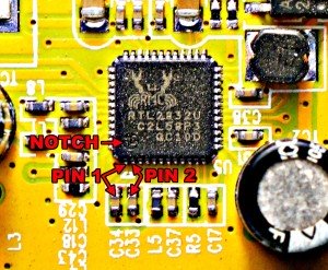
Now, one more warning - the intention is that you will have to solder two fine wires to pins #4 and #5 on the RTL2832U. This is very advanced work that requires an extremely steady hand, very good magnification and snazzy equipment. If, like me, you don’t have all three of these then you, like me, should probably connect the wires to pins #1 and #2 by cheating and using the near ends of capacitors that are attached to these pins (more on this below)
Before we start, one more external page that you must look at is http://www.rtl-sdr.com/rtl-sdr-direct-sampling-mode/
as I have stolen a bunch of information from there as well.
2) Place all the Surface mount components first
3) Attach the USB connector, SMA connectors, Jumper pins, Electrolytic caps (watch the polarity) and big LED
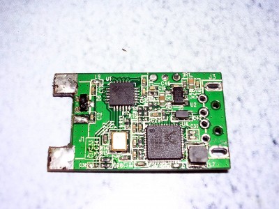
4) Take apart the dongle - the plastic case comes away like a clamshell
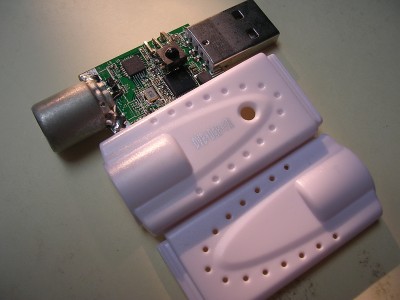
and desolder its usb and antenna connector. You will need to use desolder braid or a desolder tool for this and be careful of the central antenna connector as a bit too much force will pull the trace right off the board (actually I did that then followed up by destroying the attached SMD capacitor and had to replace it (its about 1nF).
Feel free to cut off the IR LED as it will be of no use to us.
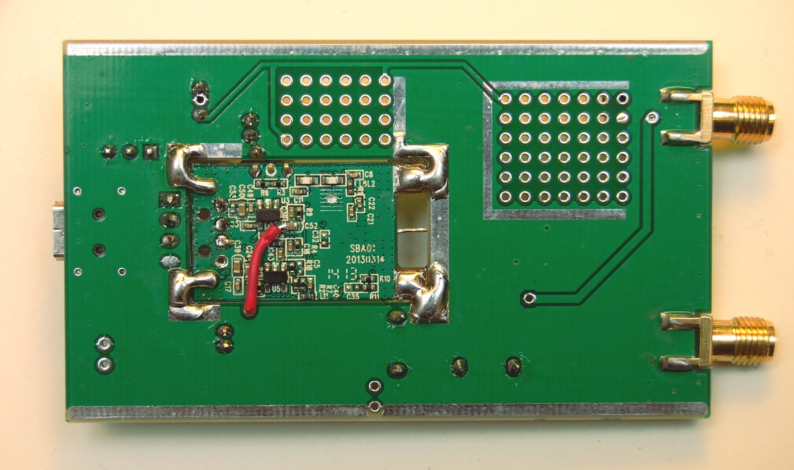
This board will then be mated with the hole in the larger breakout board. The large pads and ground pads should be covered with a thick wire or desolder braid and then connected with liberal solder to the larger board like this (image from https://imgur.com/a/Dqba2)
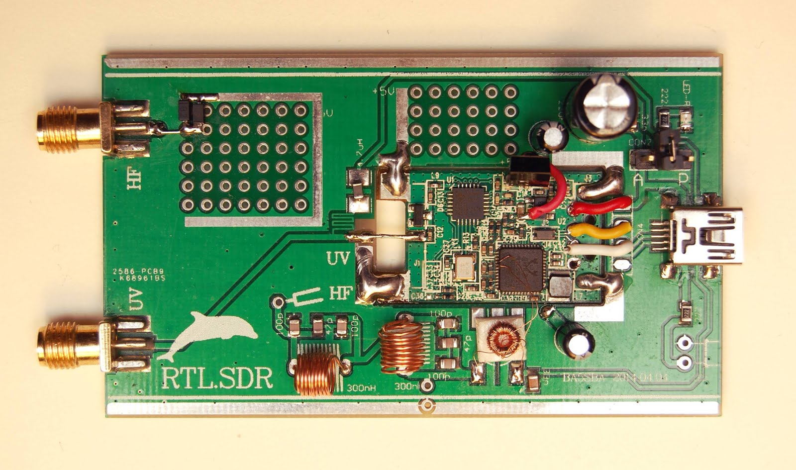
Make the crossing connections to the USB pins and the UV antenna (note insulation is not required on these jumpers)
Next we need to wind two air core inductors out of the thick wire to make a low pass filter. Straighten the wire using your fingers (so as not to scratch the enamel insulation) and use a 5mm former to wind around (a 5mm drill bit works well). Use the entire length of the wire
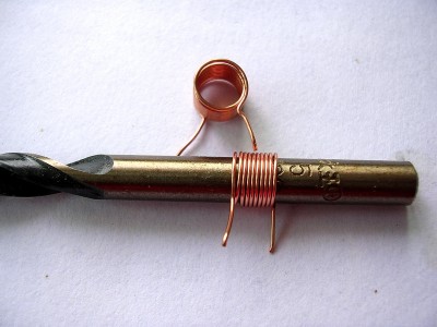
scrape the ends of the wire with a sharp blade, tin just barely with solder and solder in place. You can use the HF test point on the board across to the near landing pad of the transformer if you wish to test the filter (with a signal generator and scope or with a network analyzer) and then adjust the windings to suit - but you will probably find it pretty close if you follow the picture above leaving a “card” space between windings.
Next connect the positive side of the two electrolytic capacitors on the outside board to C47 and C52 on the inside RTL dongle. See previous picture and this picture:
Next you will be creating a transformer whose windings are two to one but its going to be made with three strands of wire - two of which are connected together (making a two to one).
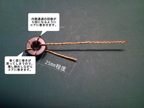
Take your fine wire and divide it into three even lengths, twist these wires together (making a trifillar wire) - this takes a little time. then wrap the wire through the toroid between 6-9 times).
from http://blog.livedoor.jp/bh5ea20tb/archives/4263275.html
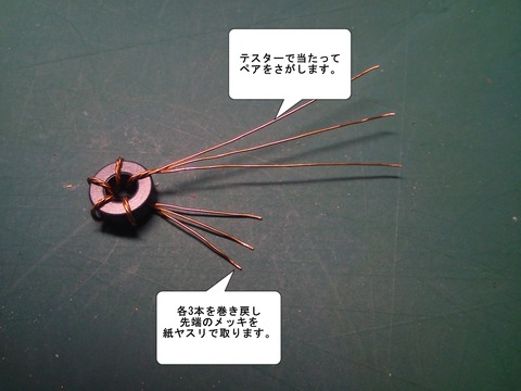
Now keep track of which end of the wire was the start and which the finish and splay the wire out into three at each end. Using a continuity tester (eg ohmeter) you must establish the identity of each wire (eg A, B, C) at each end.
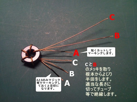
Now, the end of B and the start of C need to be joined together - I soldered them both to one of the available landing pads on the board but you may just solder them together.
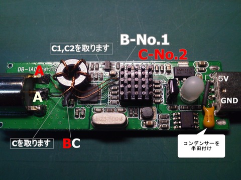
Now A at both ends will be attached in series with the HF amplifier portion near the PC board edge and the free ends of B and C (polarity here doesn’t count) attach to the pins on the RTL2832U.
NOTE: if you have never wound your own torroids or transformers with enameled wire; the most common mistake is not exposing bare wire from under the the enamel. At this thickness, a hot blob of solder will usually melt the enamel and make sufficient contact with the wire -so you MUST tin your connections. But I have found running a sharp knife over the wire ends still helps - be careful this wire is thin and breakable.
The most difficult part is now the soldering of wires B and C to the chip. As I said, I did try and finally gave up on pins 4 and 5 - I just found the position on my particular board too inaccessible behind some capacitors. I went with the older option of soldering to pins 1+2 but not directly to the pins and instead to the chip side of the two capacitors that are connected by traces to these pins - like so:
Also have a look at this schematic if its still unclear;
http://mikikg.files.wordpress.com/2012/08/rtl2832u-dc-mods.pdf
At this point you may wish to test both the UV side and the HF side connected to -say- SDR# or similar software. Remember the configuration should be for quadrature sampling when testing the VHF+ side and for direct i (pins 1+2) or direct q (pins 4+5) when testing HF.
The aluminum case is fairly straightforward - mark the connectors on the appropriate panels and cut out with drill and shape, adjust with a file.
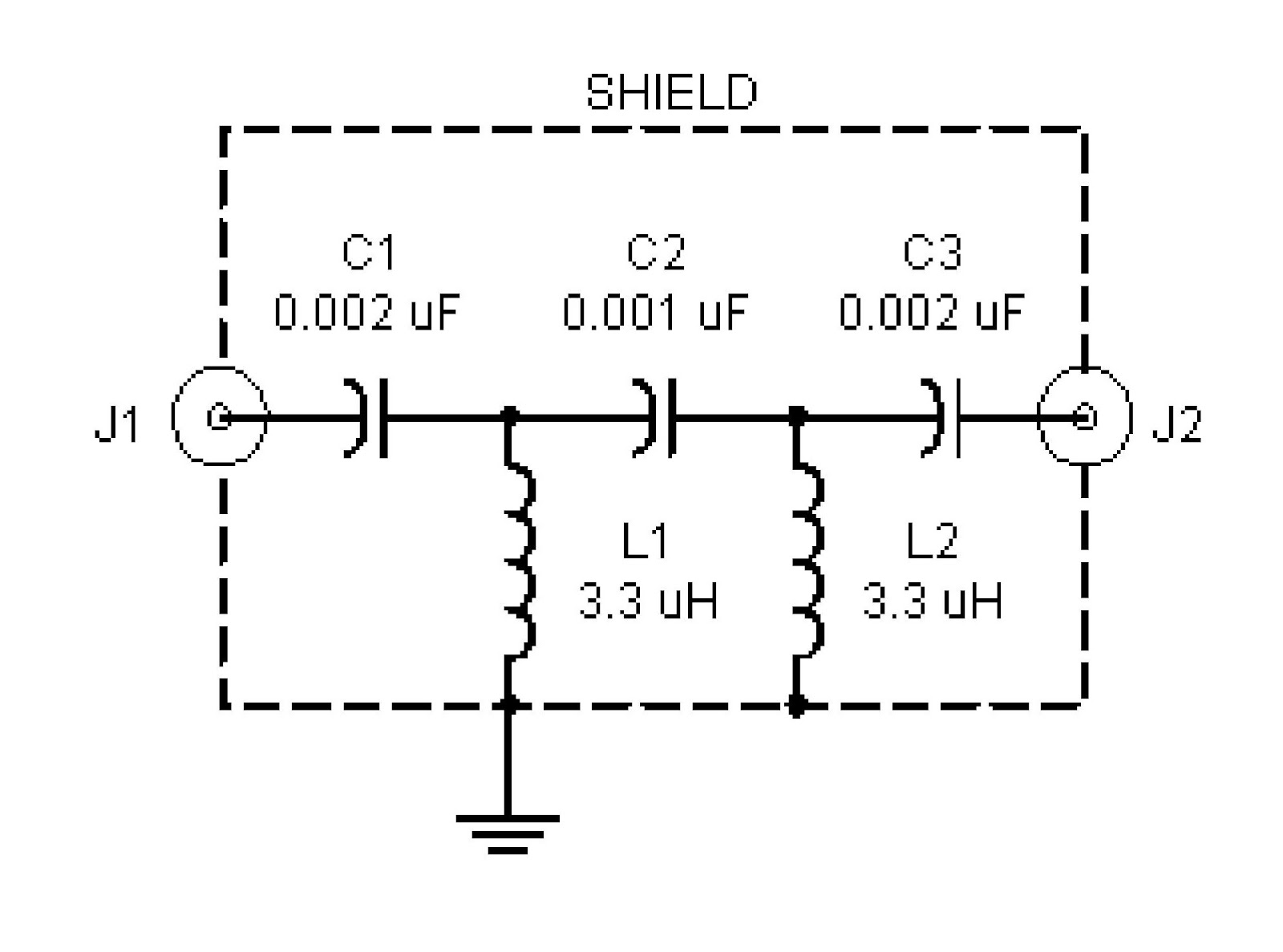
EDIT: I have found that adding an AM filter to strip out strong signals makes the unit more sensitive for the HF band. This is the simple circuit that I used (made on the extra perfboard space available on the card). This goes in series with the HF antenna in. Cut the trace with a sharp knife, scrape off the solder mask and solder J1 to the Ant in and J2 to where the lead was cut out. Keep all leads as short as possible.
Happy Listening
‘73
VA7ARI